Method of producing micromachined air-cavity resonator, micromachined air-cavity resonator, band-pass filter and oscillator using the method

Inactive Publication Date: 2010-12-09
SEOUL NAT UNIV R&DB FOUND
View PDF8 Cites 44 Cited by
  • Summary
  • Abstract
  • Description
  • Claims
  • Application Information

AI Technical Summary

Benefits of technology

[0009]An aspect of the present invention is to address at least the above mentioned problems and/or disadvantages and to provide at least the advantages described below. Accordingly, an aspect of the present invention is to provide a micromachined air-cavity resonator which is easily manufactured

Problems solved by technology

However, the conventional millimeter-wave resonators are subject to a heavy weight, a high fabrication cost, and a troublesome integration on a package substrate.
Yet, since this micromachined air-cavity resonator makes use of a typical waveguide input/output interface, it is difficult to integrate on the package substrate together with integrated passive components.
Disadvantageously, the polymer-core-conduc

Method used


Image

  • Method of producing micromachined air-cavity resonator, micromachined
air-cavity resonator, band-pass filter and oscillator using the method
  • Method of producing micromachined air-cavity resonator, micromachined
air-cavity resonator, band-pass filter and oscillator using the method
  • Method of producing micromachined air-cavity resonator, micromachined
air-cavity resonator, band-pass filter and oscillator using the method

Examples


Embodiment Construction

[0045]The following description with reference to the accompanying drawings is provided to assist in a comprehensive understanding of exemplary embodiments of the present invention as defined by the claims and their equivalents. It includes various specific details to assist in that understanding but these are to be regarded as merely exemplary. Accordingly, those of ordinary skill in the art will recognize that various changes and modifications of the embodiments described herein can be made without departing from the scope and spirit of the invention. Also, descriptions of well-known functions and constructions are omitted for clarity and conciseness.

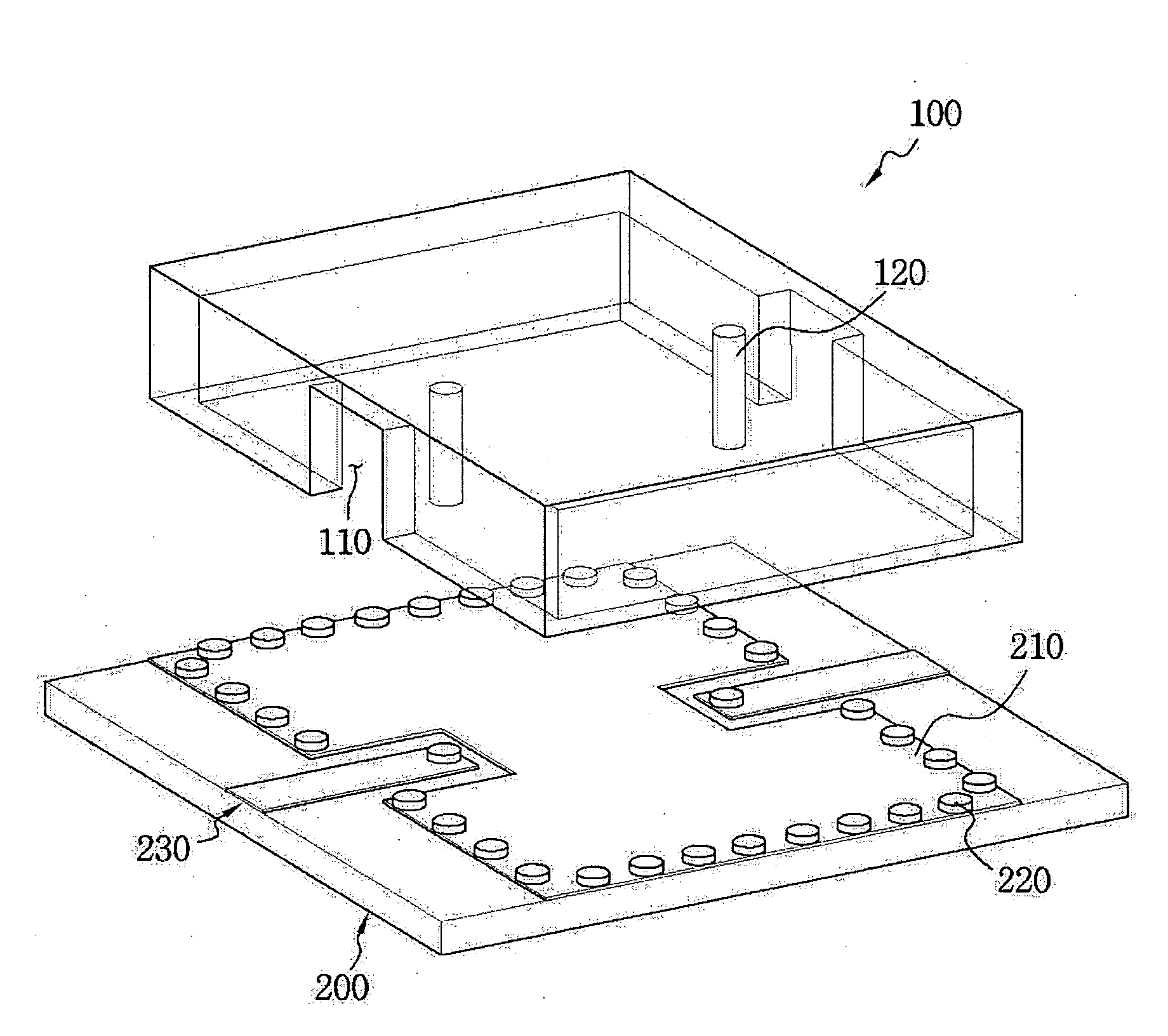
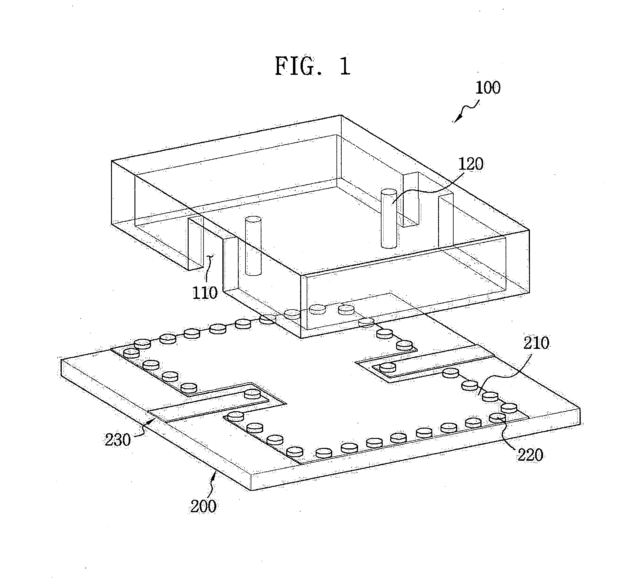
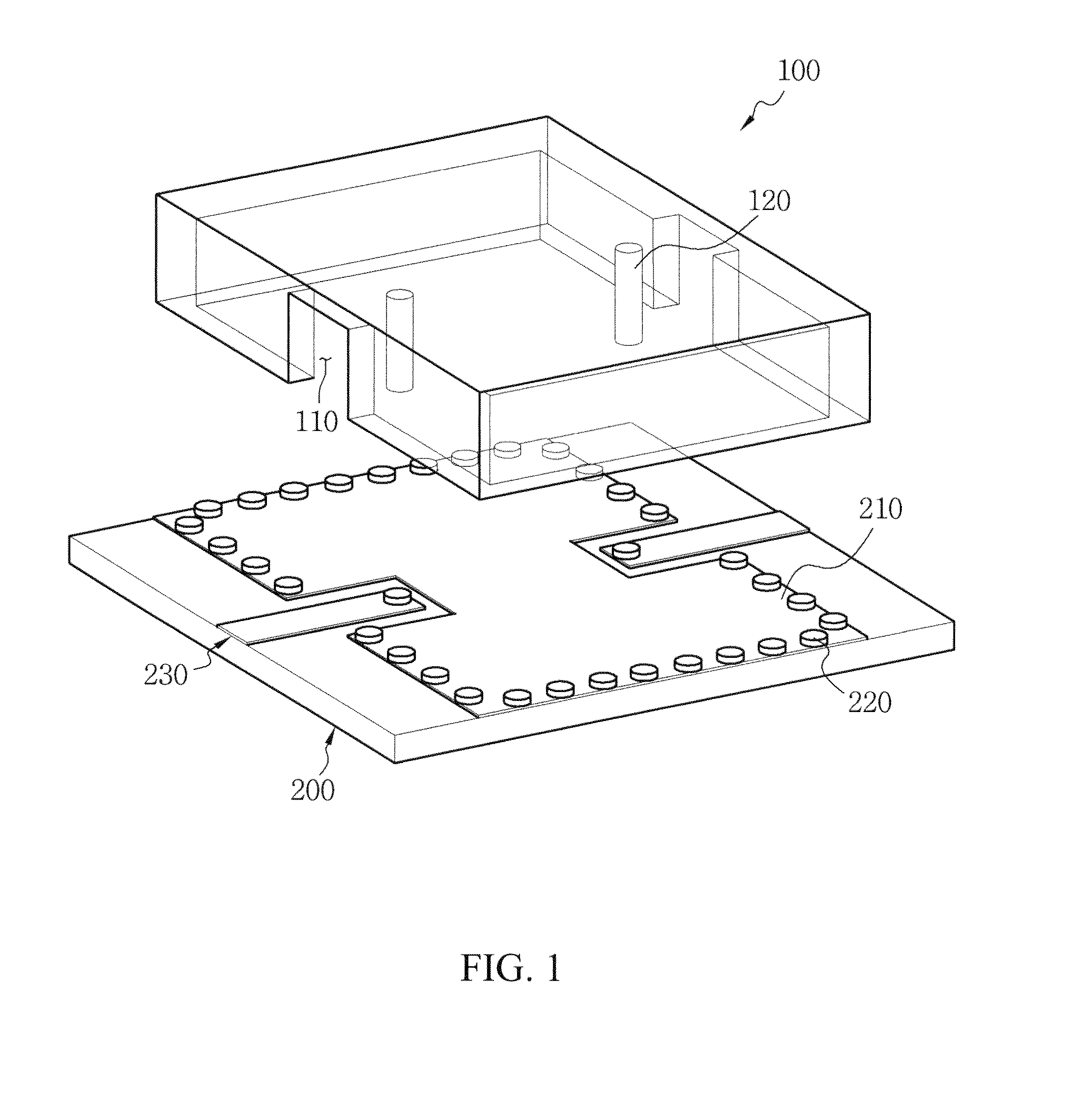
[0046]FIG. 1 depicts a geometric structure of an air-cavity resonator including a silicon current probe according to an exemplary embodiment of the present invention, FIG. 2 is a Scanning Electron Microscope (SEM) photograph of the current probe 120 and a side wall of a cavity structure, FIG. 3 is an SEM photograph of the cavity struc...


PUM


Abstract

A micromachined air-cavity resonator, a method for fabricating the micromachined air-cavity resonator, and a band-pass filter and an oscillator using the same are provided. In particular, a micromachined air-cavity resonator including a current probe fabricated together when the air-cavity resonator is fabricated, and a groove structure for rejecting detuning effect when an external circuit of a package substrate is coupled to the current probe, a millimeter-wave band-pass filter using the same, and a millimeter-wave oscillator using the same are provided. The micromachined air-cavity resonator includes a cavity structure which comprises a current probe simultaneously formed through a fabrication process, and a groove structure; and a package substrate integrated with the cavity structure. Thus, the micromachined air-cavity resonator can be easily fabricated by etching a silicon substrate and easily integrated to the package substrate using the flip-chip bonding.

Description

PRIORITY[0001]This application claims the benefit under 35 U.S.C. §119(a) to a Korean patent application filed in the Korean Intellectual Property Office on Jun. 9, 2009 and assigned Serial No. 10-2009-0050955, the entire disclosure of which is hereby incorporated by reference.BACKGROUND OF THE INVENTION[0002]1. Field of the Invention[0003]The present invention relates generally to a micromachined air-cavity resonator, a method for fabricating the micromachined air-cavity resonator, and a band-pass filter and an oscillator using the same. The micromachined air-cavity resonator, the band-pass filter, and the oscillator of the present invention are suitable for millimeter-wave applications.[0004]2. Description of the Related Art[0005]Conventional millimeter-wave resonators having a high Q value are fabricated using a metallic waveguide structure or a dielectric puck. However, the conventional millimeter-wave resonators are subject to a heavy weight, a high fabrication cost, and a trou...

Claims


Application Information

Patent Timeline
IPC IPC(8): H03B7/12H01P7/06H01L21/50H01L21/311
CPCH01P1/208H01P11/008H01P11/002H01P1/2088H01L2924/381H01P1/205H01P1/203
Inventor SONG, SANG SUBSEO, KWANG SEOK
Owner SEOUL NAT UNIV R&DB FOUND
Why Eureka
Try Eureka