Method of manufacturing permanent magnet

a technology of permanent magnets and manufacturing methods, which is applied in the direction of manufacturing tools, magnetic bodies, presses, etc., can solve the problems of inability to achieve the improvement of magnetic properties, and achieve the effect of reducing the size of raw meal powder particles and achieving the extreme superior degree of orientation

Active Publication Date: 2010-12-09
ULVAC INC
View PDF6 Cites 10 Cited by
  • Summary
  • Abstract
  • Description
  • Claims
  • Application Information

AI Technical Summary

Benefits of technology

[0019]In case the raw meal powder is for use with a rare-earth magnet and is manufactured by a quenching method, the crystal fractured surfaces can be made large in area with the raw meal powder being of angular particulate shape, and the clearance among the particles of the raw meal powder can be made small. In combination with the fact that there will be many chances of combining the crystal fractured surfaces of the raw meal powder having more equal crystal orientation relationship, the degree of orientation can be made extremely superior.

Problems solved by technology

There was thus a problem in that improvement in the magnetic properties cannot be attained.

Method used


Image

  • Method of manufacturing permanent magnet
  • Method of manufacturing permanent magnet
  • Method of manufacturing permanent magnet

Examples


example 1

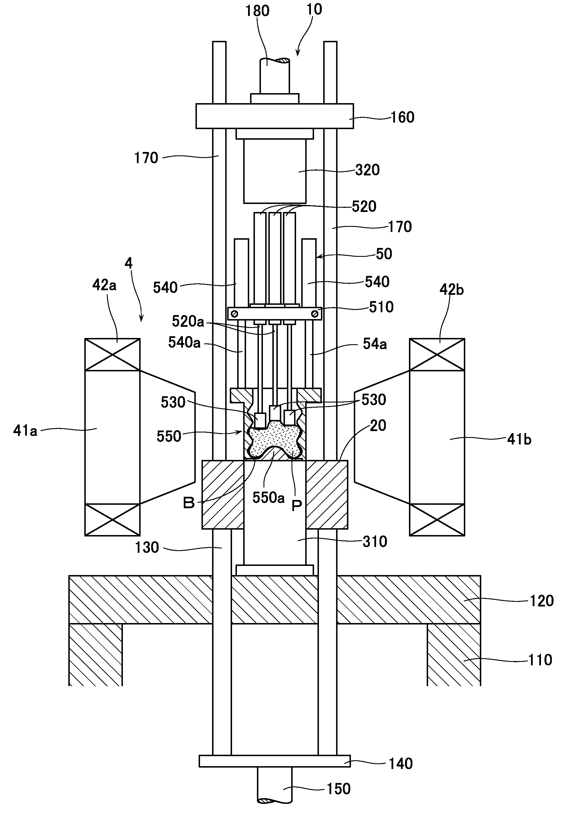
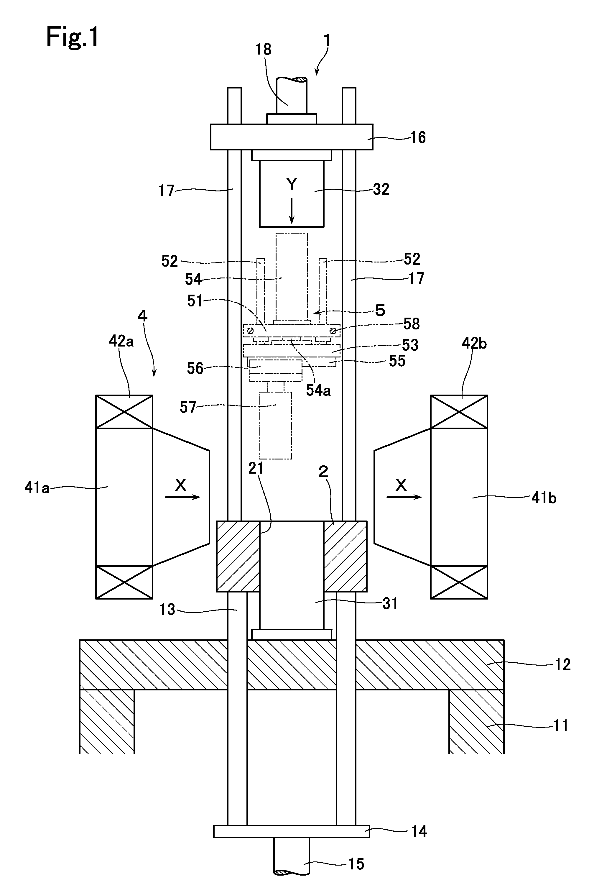
[0060]In Example 1, Nd—Fe—B based raw meal powder was manufactured as described below; orienting step and molding step were carried out by using the below-mentioned molding apparatus, thereby manufacturing a predetermined molded body; then, sintering step was carried out in which this molded body was sintered in an Ar atmosphere at a temperature of 1050° C. for three hours. As a result, there was obtained a Nd—Fe—B based sintered magnet.

[0061](Raw Meal Powder) As the Nd—Fe—B based sintered magnet, an alloy was manufactured by a strip casting method by using one whose composition was 22Nd-7Pr-0.95B-1Co-0.2Al-0.05Cu-0.1Zr-0.05Ga-bal.Fe. The alloy was then subjected to hydrogen grinding in hydrogen gas of 0.2 atmosphere for three hours (hydrogen grinding step). Then, vacuum dehydrogenation processing was carried out at 500° C. for three hours.

[0062]Successively, fine grinding was carried out in a jet mill fine grinding step to manufacture raw meal powder P having a half value width of ...

example 2

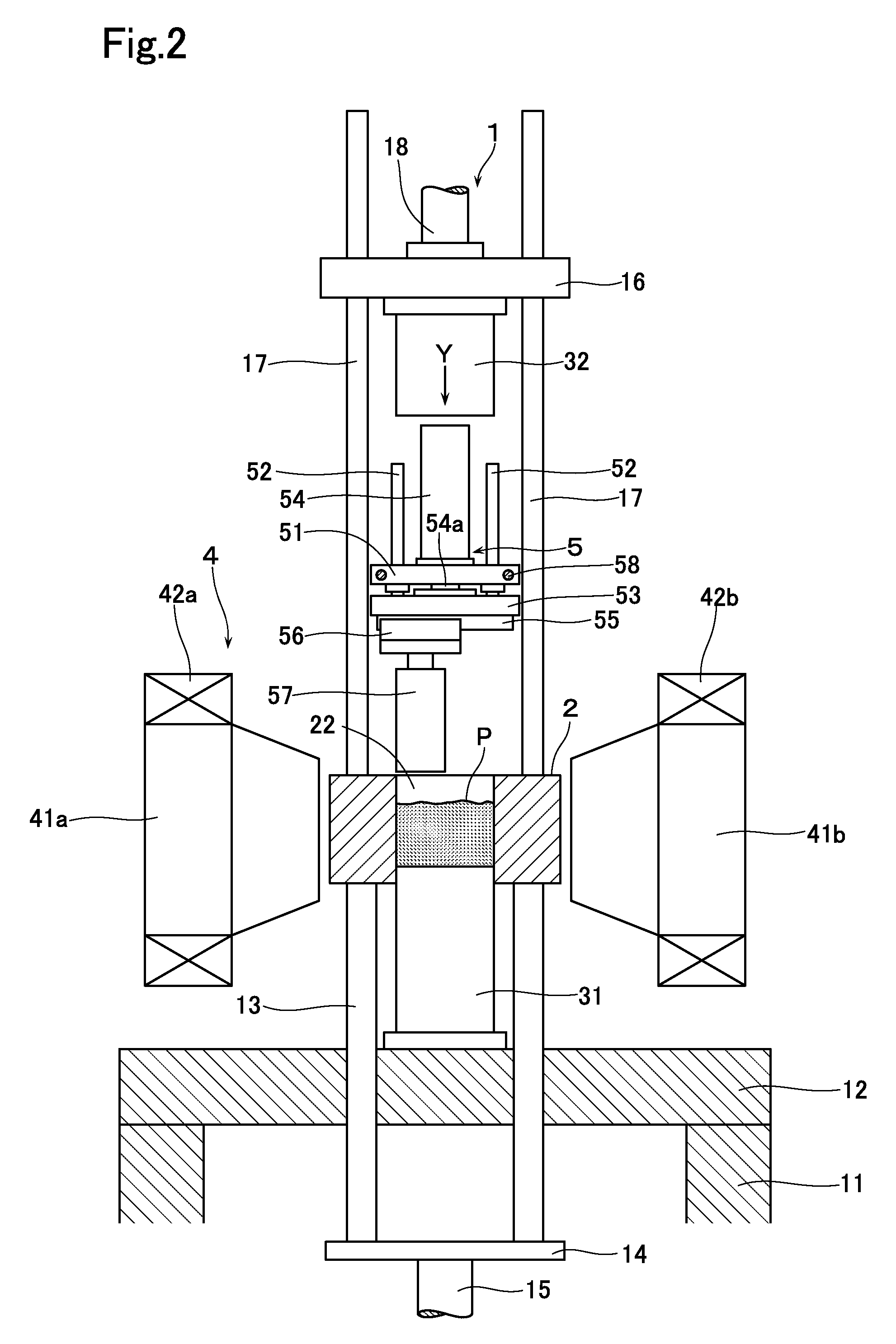
[0068]In Example 2, Nd—Fe—B based raw meal powder was manufactured as described below: orienting step and molding step were carried out by using the below-mentioned molding apparatus, thereby manufacturing a predetermined molded body; and then sintering step was carried out in which this molded body was sintered in an Ar atmosphere at a temperature of 1050° C. for three hours. As a result, there was obtained a Nd—Fe—B based sintered magnet.

[0069](Raw Meal Powder) As the Nd—Fe—B based sintered magnet, there was used one whose composition was 23Nd-7Pr-0.98B-1Co-0.2Al-0.1V-0.05Sn-bal.Fe. An alloy was manufactured by strip casting method and the alloy was then subjected to hydrogen grinding in a hydrogen gas of 0.2 atmosphere for three hours (hydrogen grinding step). Then, vacuum dehydrogenation processing was carried out at 500° C. for three hours.

[0070]Successively, the semi-finished product was subjected to fine grinding by jet mill fine grinding step. There were thus manufactured ra...


PUM

PropertyMeasurementUnit
particle size diameteraaaaaaaaaa
temperatureaaaaaaaaaa

Abstract

Crystal fractured surfaces of raw meal powder having more equal crystal orientation relationship in the magnetic field are arranged to be assembled together so that a method of manufacturing a permanent magnet which has an extremely high degree of orientation can be provided. In this invention, raw meal powder (P) is filled into a cavity, the raw meal powder (P) is oriented in the magnetic field while being pressed or urged by pressing means that has a smaller area than the cross-sectional area of the cavity. Semi-finished product thus oriented is compression-molded into a predetermined shape in the magnetic field.

Description

TECHNICAL FIELD[0001]The present invention relates to a method of manufacturing a permanent magnet and more particularly relates to a method to be used in manufacturing a Nd—Fe—B based magnet having a high degree of orientation.BACKGROUND ART[0002]A Nd—Fe—B based sintered magnet (so-called neodymium magnet) is made of a combination of iron and elements of Nd and B that are inexpensive and abundant natural resources and stably obtainable, and can thus be manufactured at a low cost and additionally has high magnetic properties (its maximum energy product is about 10 times that of ferritic magnet). Accordingly, the Nd—Fe—B based sintered magnets have been used in various kinds of articles such as electronic devices and have recently come to be adopted in motors and electric generators for hybrid cars. The amount of their uses is on the increase.[0003]The Nd—Fe—B based magnets are mainly manufactured in a powder metallurgy method. In this method, Nd, Fe, and B are first formulated in a ...

Claims


Application Information

Patent Timeline
Patent Type & Authority Applications(United States)
IPC IPC(8): B22F1/00B22F3/02B22F3/12
CPCB22F3/02B22F2998/10B22F2999/00B30B11/027H01F1/0577H01F41/0273B22F9/08B22F9/023B22F2009/044B22F3/093B22F3/087B22F3/1025B22F2003/023B22F2003/033
Inventor NAGATA, HIROSHISHINGAKI, YOSHINORI
Owner ULVAC INC
Why Eureka
Try Eureka