
Marine power splitting gearbox

a technology of power splitting gearbox and gearbox, which is applied in the direction of gearing, vessel parts, vessel construction, etc., can solve the problems of increasing the design cost and complexity of the system, difficulty in controlling marine vessels at times, and difficulty in identifying or rolling experience, so as to increase the propulsion efficiency of the system, less boat draft, and the effect of increasing the pitch/diameter ratio coefficien

Inactive Publication Date: 2010-12-09
TWIN DISC
View PDF29 Cites 9 Cited by
  • Summary
  • Abstract
  • Description
  • Claims
  • Application Information

AI Technical Summary

Benefits of technology

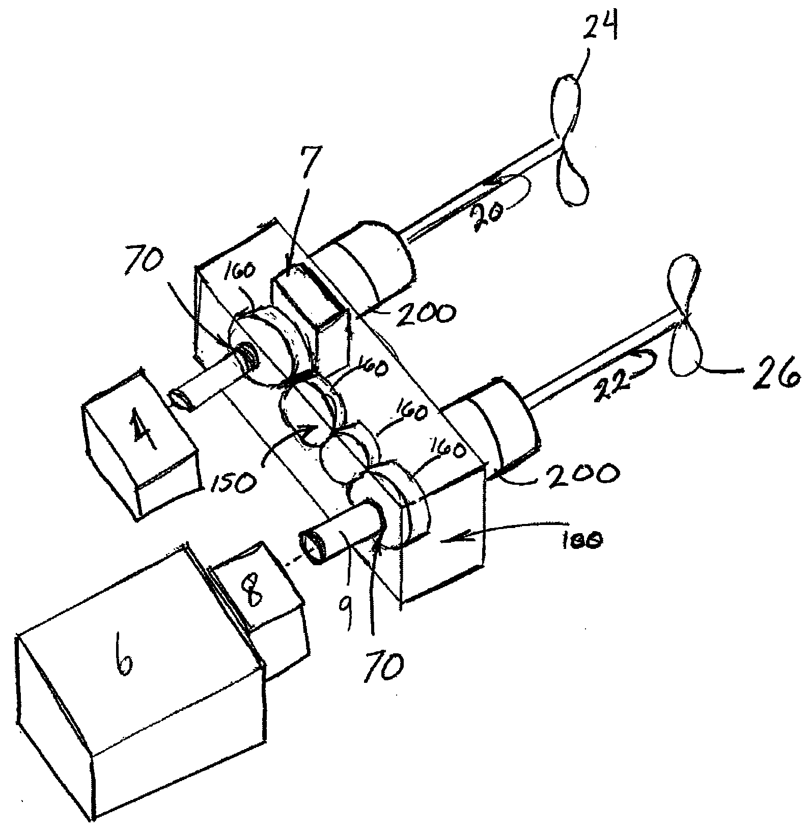
[0010]The present invention is directed to a power splitting gearbox for use with a marine powertrain system of a marine vessel. The preferred embodiments provide a marine power splitting gearbox that can incorporate existing final drive assemblies while providing counter-rotating propellers that are driven with fewer engines than the total number of propellers. By splitting the power output from a single prime mover for distribution through two final drive assemblies that counter-rotate a pair of propellers, smaller final drive assemblies can be implemented since they only require a half-torque or power capacity as compared to the total torque or power output of the prime mover. Smaller final drive assemblies can use smaller diameter propellers with a higher pitch / diameter ratio coefficient that increases propulsion efficiency of the system. Such feature can also lead to less boat draft and improved handling of the marine vessel.
[0013]The present invention is also directed to a marine power splitting propulsion system. The system includes a power splitting gear gearbox inputting power from a prime mover and dividing the power into multiple power components. Multiple final drives are operably connected to the power splitting gearbox. Each of the multiple final drives imputing a respective one of the multiple torque or power components such that each of the multiple final drives can be subjected to less than the entire power provided by the prime mover, allowing relatively smaller, less expensive, and more hydrodynamic final drives, to be incorporated, as compared to if each final drive was required to handle the entire torque or power output of the engine. Multiple clutch assemblies are provided between the multiple final drives and the power splitting gearbox such that the power inputted from the prime mover can be directed to a single one of the multiple final drives.
[0014]The marine power splitting propulsion system according the present embodiment may be configured such that each of the final drives is a surface drive assembly. The multiple surface drive assemblies may be articulatable for trimming and steering a marine vessel incorporating the marine power splitting propulsion system according to the present embodiment. The multiple surface drive assemblies may include a first surface drive assembly that rotates a first propeller in a first direction and a second surface drive assembly that rotates a second propeller in a second, opposite, direction. At least one of the multiple clutch assemblies may be modulatable thereby allowing the power from the prime mover to be variably divided into the multiple power components.

Problems solved by technology

Marine vessels having multiple engines that drive multiple propellers in the same direction of rotation can also experience listing or rolling due to propeller torque effect.
Propeller torque induced listing and rolling can make controlling marine vessels difficult at times.
This can lead to added expense and complexity of the design of the systems, since the components, including geometry, of the starboard side powertrain and the port side powertrain are not identical.
Accordingly, marine vessels that utilize high torque or power outputting engines require final drive assemblies that are quite large, heavy, and expensive.
However, providing contra-rotating propellers typically requires a concentrically arranged pair of drive shafts, whereby the outer drive shaft must be hollow which can compromise its strength and add expense and complexity to the design.
Each of the prior systems fail to provide a solution to the problem of providing a highly efficient yet strong and compact marine drive system that uses multiple propellers in high powered marine applications.

Method used


Image

  • Marine power splitting gearbox
  • Marine power splitting gearbox
  • Marine power splitting gearbox

Examples


Embodiment Construction

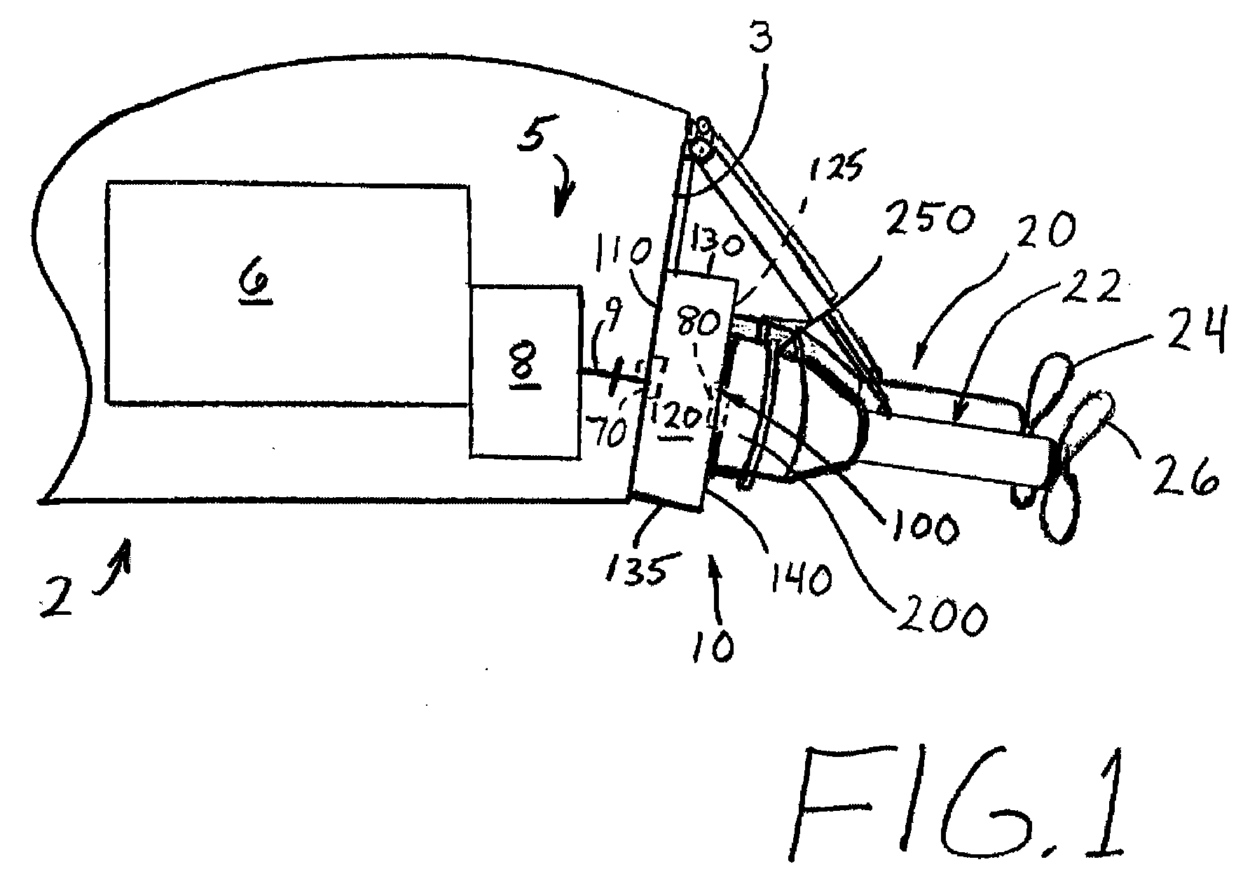
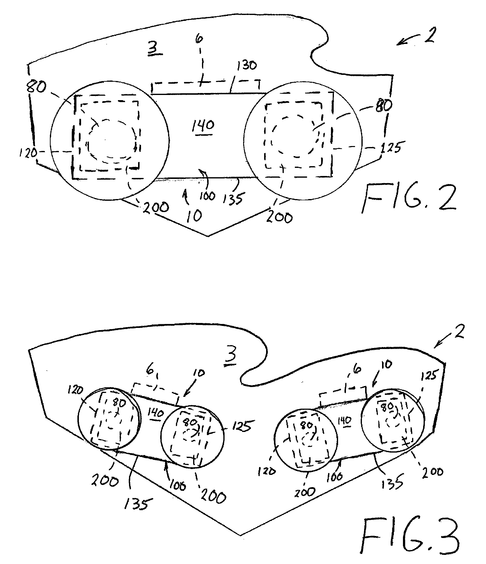
[0029]With reference now to the drawings, and particularly to FIG. 1, there is shown a cross-sectional schematic view of an aft portion of a marine vessel 2 that has a transom 3 and includes a powertrain system 5. The powertrain system 5 utilizes one or more prime mover 6 that is preferably an internal combustion engine. A transmission 8 is operably connected to the prime mover 6, behind or downstream of the prime mover 6. Transmission 8 is preferably an MGX-series transmission (QuickShift® transmission) or an MG-series transmission, available from Twin Disc, Inc. headquartered in Racine, Wis. Each series of prime mover 6 and transmission 8 is connected to a power splitting gearbox 10, for example by way of a transmission output shaft 9. Power splitting gearbox 10 converts power that is delivered from the prime mover 6 into multiple power components for counter-rotating a pair of propellers 24, 26 provided on a pair of final drive assemblies 20, 22, respectively. Each final drive as...


PUM


Abstract

A power splitting gearbox is provided that allows a single prime mover to distribute power, for example torque, to multiple final drive assemblies, such as surface drives or other final drives. The power splitting gearbox can be provided downstream from a marine transmission and can be mounted directly to a transom of a marine vessel. The gearbox can have a back wall that accepts and supports mounting surfaces of the multiple final drive assemblies such that the gearbox bears the weight of the multiple final drive assemblies. The gearbox has two outputs that rotate in opposing directions so that a pair of final drive assemblies mounted to the gearbox will counter-rotate a pair of propellers for providing a propulsive force that moves the marine vessel.

Description

BACKGROUND OF THE INVENTION[0001]1. Field of the Invention[0002]The present invention relates generally to marine powertrains and more specifically to systems for transmitting power from prime movers to propulsion devices, such as propellers.[0003]2. Discussion of the Related Art[0004]It is known that a marine vessel having a single engine that drives a single propeller can experience a propeller torque effect that forces the marine vessel to list or roll. Marine vessels having multiple engines that drive multiple propellers in the same direction of rotation can also experience listing or rolling due to propeller torque effect. Propeller torque induced listing and rolling can make controlling marine vessels difficult at times.[0005]Accordingly, some marine vessels include a pair of engines and transmissions that rotate a pair of propellers in opposite directions. This configuration is conventionally referred to as counter-rotating propellers and it can reduce such propeller torque e...

Claims


Application Information

Patent Timeline
IPC IPC(8): B63H20/14
CPCB63H23/06B63H23/28B63H2023/065B63H2023/062B63H23/30B63H23/02B63H23/10F16H37/02F16H57/02
Inventor ROLLA, PHILIPWILSON, MARK B.
Owner TWIN DISC
Learn More