Carbon nanotube-based solar cells

a carbon nanotube and solar cell technology, applied in the field of solar cells, can solve the problems of reducing the efficiency of such cells, affecting the efficiency of solar cells, so as to reduce the rate of electron-hole recombination and efficient removal

Inactive Publication Date: 2010-12-16
APPLIED MATERIALS INC
View PDF17 Cites 24 Cited by
  • Summary
  • Abstract
  • Description
  • Claims
  • Application Information

AI Technical Summary

Benefits of technology

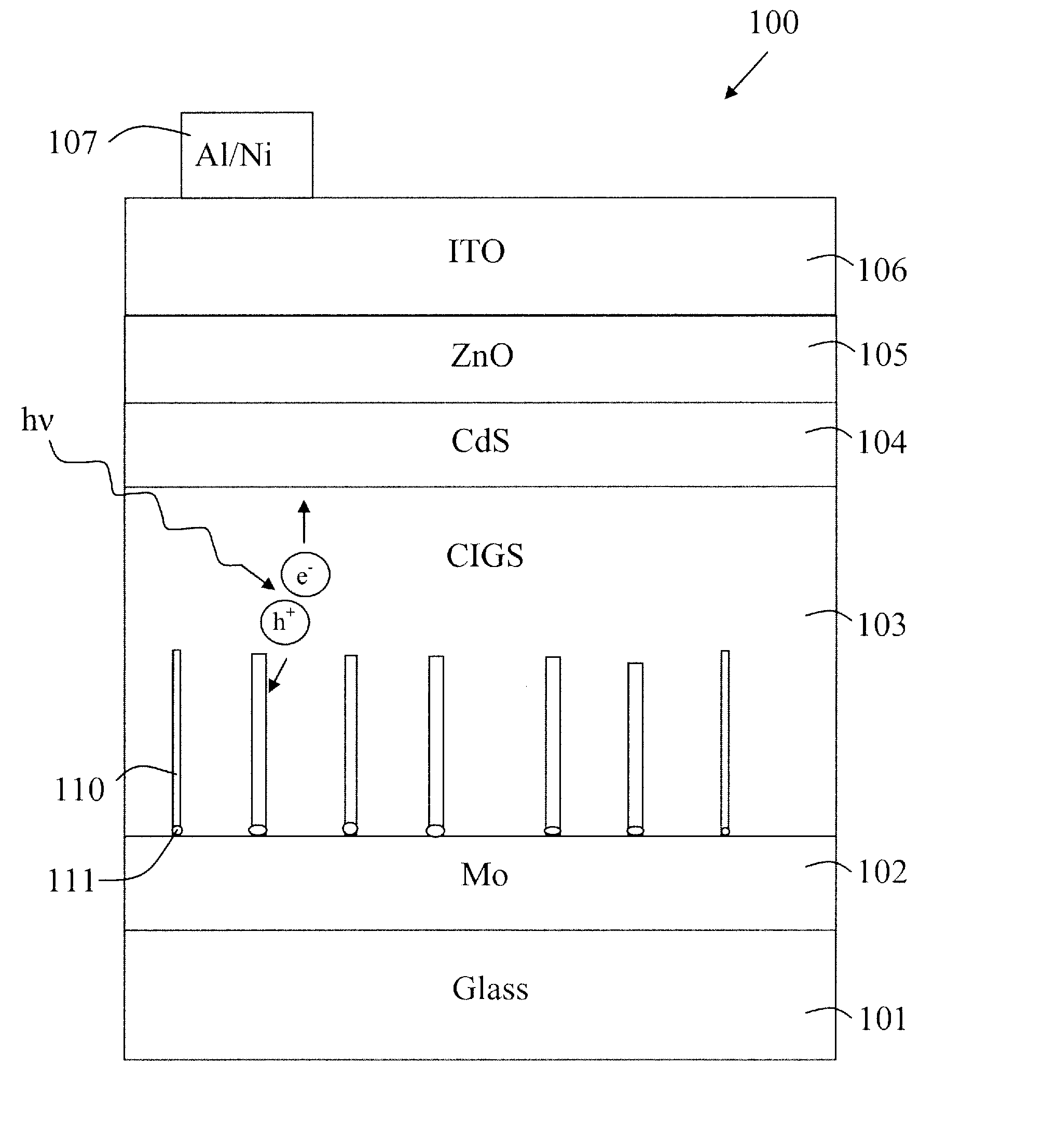
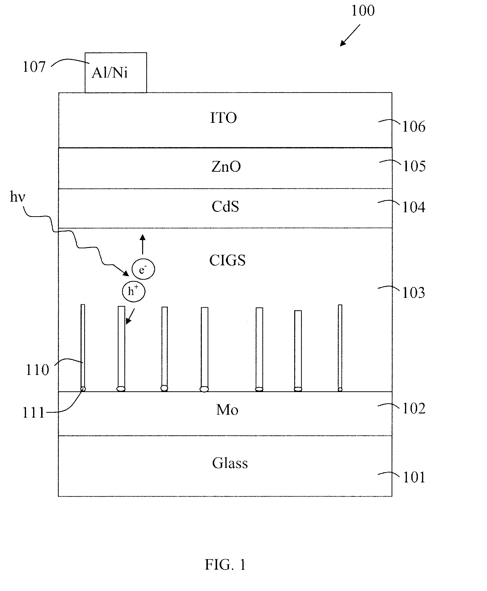
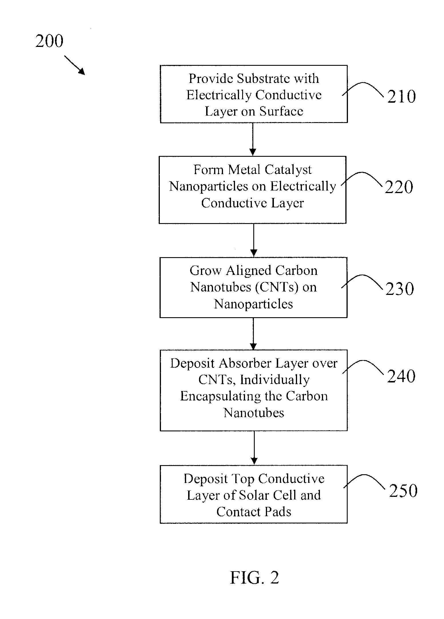
[0007]In general, embodiments of this invention provide solar cells with carbon nanotubes (CNTs) which are used: to define a micron / sub-micron geometry of the solar cells; and / or as charge transporters for efficiently removing charge carriers from the absorber layer to reduce the rate of electron-hole recombination in the absorber layer. The density of the CNTs may be controlled and the CNTs may be patterned—into bundles, for example.

Problems solved by technology

The result is a difficult compromise between these two opposing effects and the efficiency of such cells is less than optimal.
However, absorber layers are often defective materials with densities of recombination sites that have a significant effect on the efficiency of the solar device.
Furthermore, for amorphous silicon solar cells there is an additional problem called the Staebler-Wronski effect, which is a degradation of performance over time, and the degradation is greater for thicker amorphous silicon films.
However, light induced degradation of an amorphous silicon based solar cell depends not only on thickness, but also on the growth rate of the amorphous silicon, the deposition parameters, etc.
While promising results have been obtained for such solar cell structures, the fabrication of these cells is difficult on an industrial scale.

Method used


Image

  • Carbon nanotube-based solar cells
  • Carbon nanotube-based solar cells
  • Carbon nanotube-based solar cells

Examples


Embodiment Construction

[0028]Embodiments of the present invention will now be described in detail with reference to the drawings, which are provided as illustrative examples of the invention so as to enable those skilled in the art to practice the invention. Notably, the figures and examples below are not meant to limit the scope of the present invention to a single embodiment, but other embodiments are possible by way of interchange of some or all of the described or illustrated elements. Moreover, where certain elements of the present invention can be partially or fully implemented using known components, only those portions of such known components that are necessary for an understanding of the present invention will be described, and detailed descriptions of other portions of such known components will be omitted so as not to obscure the invention. In the present specification, an embodiment showing a singular component should not be considered limiting; rather, the invention is intended to encompass ...


PUM

PropertyMeasurementUnit
temperatureaaaaaaaaaa
lengthaaaaaaaaaa
thickaaaaaaaaaa

Abstract

Solar cells are provided with carbon nanotubes (CNTs) which are used: to define a micron/sub-micron geometry of the solar cells; and/or as charge transporters for efficiently removing charge carriers from the absorber layer to reduce the rate of electron-hole recombination in the absorber layer. A solar cell may comprise: a substrate; a multiplicity of areas of metal catalyst on the surface of the substrate; a multiplicity of carbon nanotube bundles formed on the multiplicity of areas of metal catalyst, each bundle including carbon nanotubes aligned roughly perpendicular to the surface of the substrate; and a photoactive solar cell layer formed over the carbon nanotube bundles and exposed surfaces of the substrate, wherein the photoactive solar cell layer is continuous over the carbon nanotube bundles and the exposed surfaces of the substrate. The photoactive solar cell layer may be comprised of amorphous silicon p/i/n thin films; although, concepts of the present invention are also applicable to solar cells with absorber layers of microcrystalline silicon, SiGe, carbon doped microcrystalline silicon, CIS, CIGS, CISSe and various p-type II-VI binary compounds and ternary and quaternary compounds.

Description

CROSS-REFERENCE TO RELATED APPLICATIONS[0001]This application claims the benefit of U.S. Provisional Application Ser. No. 61 / 185,928 filed Jun. 10, 2009 and U.S. Provisional Application Ser. No. 61 / 303,617 filed Feb. 11, 2010.FIELD OF THE INVENTION[0002]The present invention relates generally to solar cells, and more particularly to solar cells comprising carbon nanotubes.BACKGROUND OF THE INVENTION[0003]Solar cells comprise an absorber layer where photons are absorbed and generate electron-hole pairs. The absorber layer of planar thin film solar cells needs to be thick enough for most of the incident photons to be captured but not so thick that all the charge carriers produced by photon absorption have either recombined or have been trapped before they reach the solar cell electrodes and generate photocurrent. The result is a difficult compromise between these two opposing effects and the efficiency of such cells is less than optimal.[0004]Absorber layers may be comprised of materi...

Claims


Application Information

Patent Timeline
Patent Type & Authority Applications(United States)
IPC IPC(8): H01L31/04H01L31/18C23C16/22
CPCB82Y10/00H01L31/022425H01L31/0322H01L31/0384H01L31/0749H01L51/0048H01L51/4213Y02E10/541Y02P70/521H01L31/03529Y02P70/50H10K85/221H10K30/10
Inventor NALAMASU, OMKARAMGAY, CHARLESPUSHPARAJ, VICTOR L.SINGH, KAUSHAL K.VISSER, ROBERT J.FOAD, MAJEED A.HOFMANN, RALF
Owner APPLIED MATERIALS INC
Why Eureka
Try Eureka