Integrated multi-band antenna module

a multi-band antenna and integrated technology, applied in the field of multi-band antennas, can solve the problems of noise to each other, damage to outer appearance and usage, signal dropout,

Inactive Publication Date: 2010-12-16
WELL GREEN TECH
View PDF12 Cites 16 Cited by
  • Summary
  • Abstract
  • Description
  • Claims
  • Application Information

AI Technical Summary

Benefits of technology

[0011]Therefore, the primary object of the present invention is to provide an integrated multi-band antenna module using a mirror effect, capacitive coupling effect, arrangement of different plane antennas with proper separations and best matched impedances so as to have a better performance with multiple operating frequencies and operation for ultra wide bandwidth.
[0012]A secondary object of the present invention is to provide an arrangement of the least antennas on an insulated plane to achieve a lowest reflection loss and a minimization of size.
[0013]A yet object of the present invention is to provide an antenna module with large-scaled conducting top plate to compensate weak signals, to raise radiating effect, to achieve low band resonance, also to form a combined mirror antenna.
[0019]Relative gaps between the first conducting top plate (321) and the first ground line (34), the second conducting top plate (413) and the second ground line (45), the third conducting top plate (423) and the second ground line (45), the fourth conducting top plate (614) and the third ground line (65), the fifth conducting top plate (623) and the third ground line (65), the sixth conducting top plate (711) and the fourth ground line (74), the seventh conducting top plate (721) and the fourth ground line (74) form the capacitive coupling effect so as to receive optimized frequencies and capable of lowering the reflection loss.

Problems solved by technology

The problem usually happens indoors.
But in fact, signals will be reflected hundreds of times by various surfaces and the signal dropout happens.
1. While multiple operating frequencies are applied to the combined antenna of the prior art, improper separations between antennas will cause noises to each other.
2. Too many antennas are added for applying various operating frequencies will damage an outer appearance and an usage.
3. The prior combined antenna is not suitable for ultra high bandwidth operation.
4. The prior art with high matched impedance and high reflection loss is a waste of time and cost.

Method used


Image

  • Integrated multi-band antenna module
  • Integrated multi-band antenna module
  • Integrated multi-band antenna module

Examples


Embodiment Construction

[0024]In order that those skilled in the art can further understand the present invention, a description will be provided in the following in details. However, these descriptions and the appended drawings are only used to cause those skilled in the art to understand the objects, features, and characteristics of the present invention, but not to be used to confine the scope and spirit of the present invention defined in the appended claims.

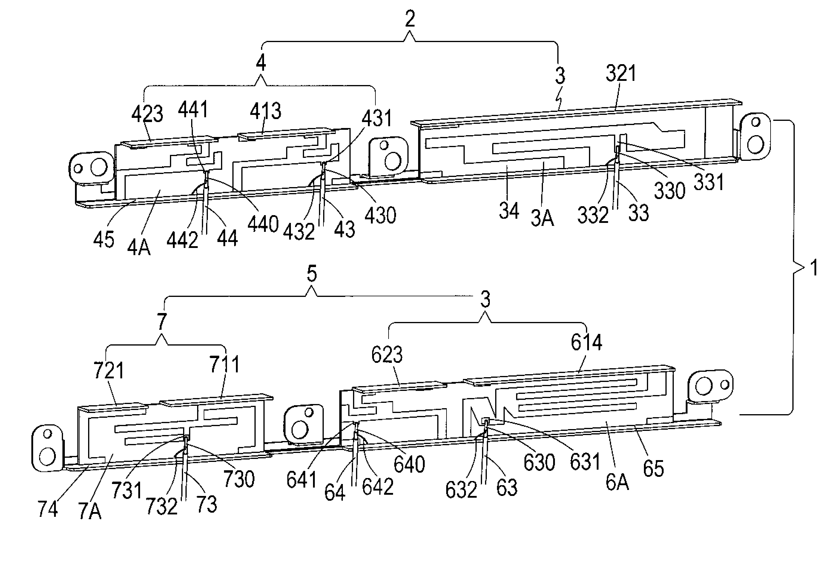
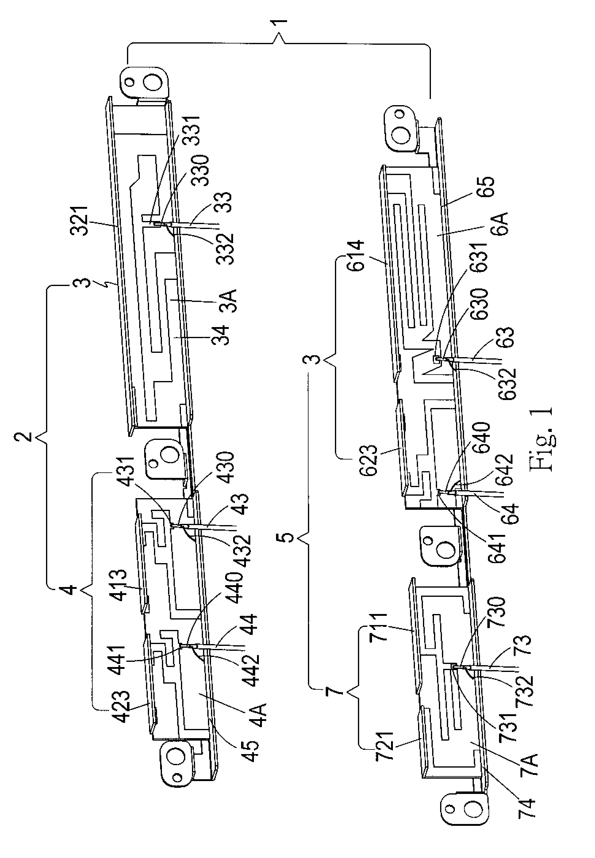
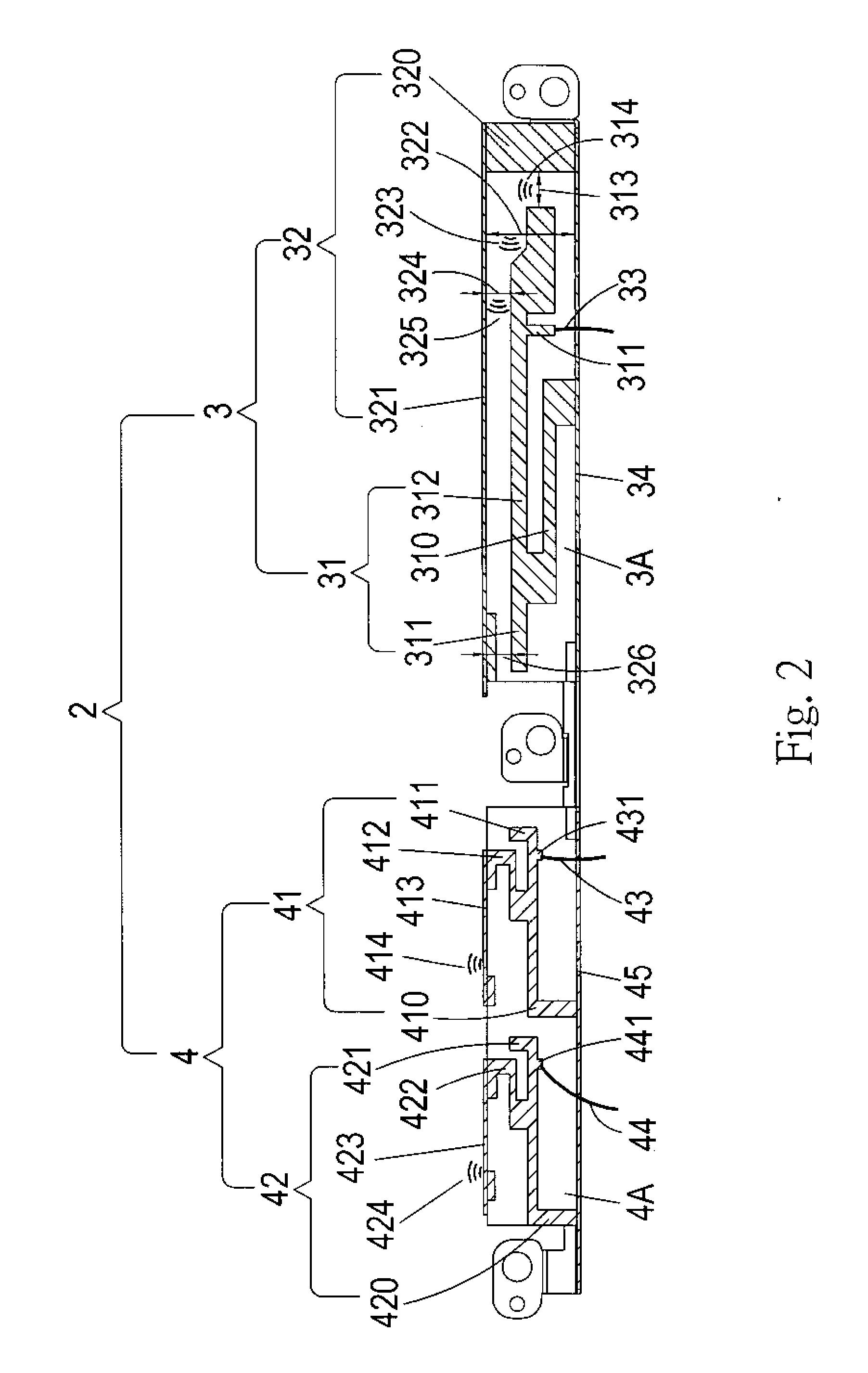
[0025]Referring to FIGS. 1 to 3, the outer appearance of a first antenna body and a second antenna body of an integrated multi-band antenna module according to the present invention are illustrated. The integrated multi-band antenna module 1 includes:

[0026]A first antenna body 2 has a first body 3 including: a first radiating portion 31; conductor being arranged onto a first insulated plane 3A, a first arm 310 made of the conductor being formed as an approximate rotated S shape; a lower end of the first arm 310 being connected to a meddle section o...


PUM


Abstract

An integrated multi-band antenna module includes a first antenna body having a first body and a second body, and a second antenna body having a third body and a fourth body. The first to the fourth body have relative radiating portions, feed lines, and ground lines. The radiating portions have relative arms, antenna portions, feed arms, and conducting top plates. Resonant excitation sources are formed by capacitive coupling effects from gaps between the above components. The capacitive coupling effects also lower the inductance effect and the reflection loss. Mirror effect and large-scaling conducting top plates are used to raise a radiating effect. The relative gaps form the capacitive coupling effects to receive optimized frequencies so that a small-size integrated antenna with multi-band, high radiating effect, good resonant effect, and suitable for an ultra wide bandwidth operation is achieved.

Description

FIELD OF THE INVENTION[0001]The present invention relates to a multi-band antenna, and particular to an integrated multi-band antenna module using a mirror effect, capacitive coupling effect, arrangement of different plane antennas with proper separations and best matched impedances so as to have a better performance with multiple operating frequencies and operation for ultra wide bandwidth.DESCRIPTION OF THE PRIOR ART[0002]Communication systems using a Radio Frequency (RF) for transmitting signals will encounter an effect under multi-path transmission. The target signal from a source is reflected by objects so that the signals transmitted from multiple pathes are received by an antenna. Signal dropout will happen because of neutralizations between different phases of multi-path signals. The problem usually happens indoors. An indoor wireless system emits signals in any directions, and the direct signal is the strongest signal. But in fact, signals will be reflected hundreds of time...

Claims


Application Information

Patent Timeline
Patent Type & Authority Applications(United States)
IPC IPC(8): H01Q1/38H01Q5/00H01Q5/371H01Q5/378H01Q5/40
CPCH01Q1/38H01Q5/00H01Q9/42H01Q5/371H01Q5/378H01Q5/40
Inventor CHANG, PAO-SUIWU, YU-SHENG
Owner WELL GREEN TECH
Why Eureka
Try Eureka