X-ray imaging apparatus, x-ray imaging method and method of controlling x-ray imaging apparatus

a technology of x-ray imaging and x-ray imaging apparatus, which is applied in the direction of material analysis using wave/particle radiation, nuclear engineering, and using mechanical means, etc., can solve problems such as errors and device use, and achieve the effect of reducing error factors, and reducing device use costs

Active Publication Date: 2010-12-16
CANON KK
View PDF2 Cites 14 Cited by
  • Summary
  • Abstract
  • Description
  • Claims
  • Application Information

AI Technical Summary

Benefits of technology

[0009]In view of the above-identified circumstances, it is therefore an object of the present invention to provide an X-ray imaging apparatus, an X-ray imaging method and a method of controlling such an X-ray imaging apparatus that can simplify the device and computationally determine effective atomic numbers for light elements with small error factors.
[0012]Thus, according to the present invention, there are provided an X-ray imaging apparatus, an X-ray imaging method and a method of controlling such an X-ray imaging apparatus that can simplify the device and computationally determine effective atomic numbers with small error factors even for light elements.

Problems solved by technology

However, the method described in Japanese Patent Application Laid-Open No. 2007-082663 is accompanied by a problem that a complex device needs to be used for the method because X-rays having two or more wavelengths need to be indispensably employed.
Additionally, since the method described in the above-cited Patent Document cannot obtain a sufficient contrast for light elements so that it can give rise to errors because it only utilizes an absorption contrast image.

Method used


Image

  • X-ray imaging apparatus, x-ray imaging method and method of controlling x-ray imaging apparatus
  • X-ray imaging apparatus, x-ray imaging method and method of controlling x-ray imaging apparatus
  • X-ray imaging apparatus, x-ray imaging method and method of controlling x-ray imaging apparatus

Examples


first embodiment

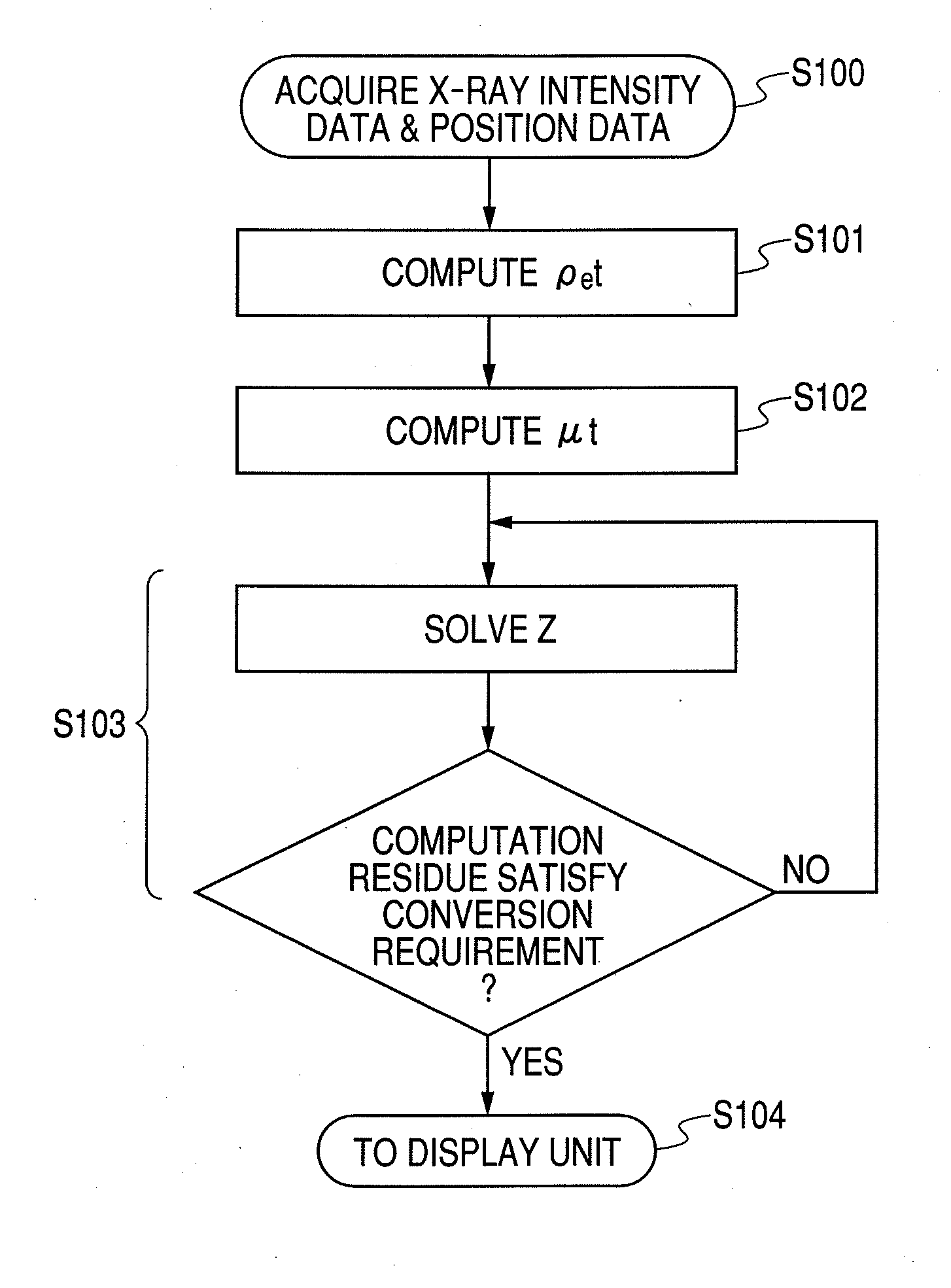
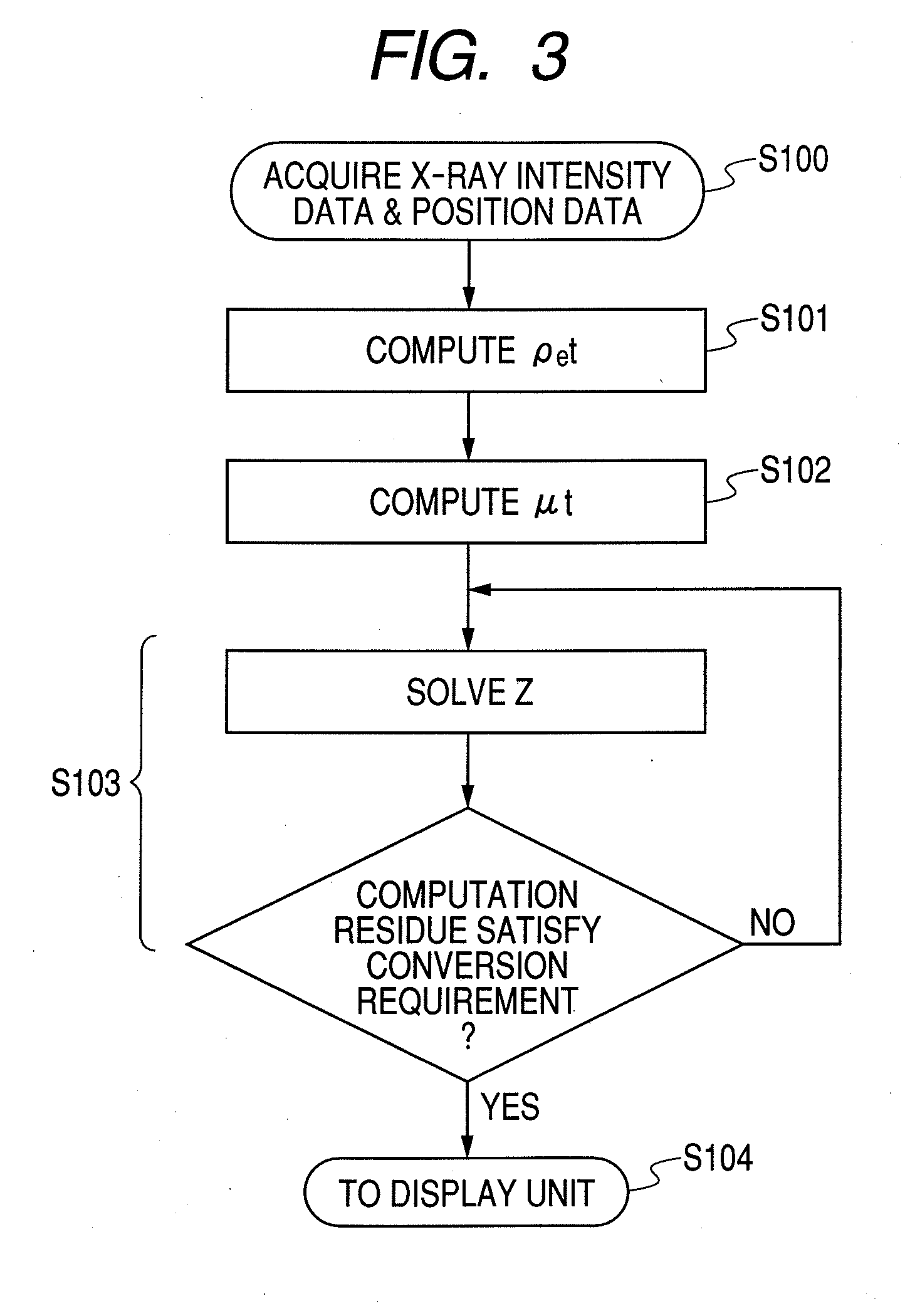
[0024]An imaging apparatus and an image pickup method for acquiring the effective atomic number distribution by utilizing the quantity of X-ray phase and the X-ray transmittance will be described here.

[0025]The complex refractive index of X-ray relative to a substance is expressed by formula (1) illustrated below.

n=1−δ−iβ  (1)

[0026]The real part in the formula (1) is a term corresponding to phase and the imaginary part is a term corresponding to absorption. For the X-ray absorption of an object of examination, the linear attenuation coefficient μ and the imaginary part β of the complex refractive index of the formula (1) can be defined by formula (2) illustrated below:

μt=4πλ∫βt,(2)

where λ is the X-ray wavelength, which is the effective wavelength when continuous X-rays are used. The symbol t represents the thickness of the object of examination.

[0027]When the intensity of transmitted X-rays is observed by means of an X-ray detector and if the intensity of X-rays is Io in an instance...

second embodiment

[0057]Since the thickness t of the object of examination is unknown, an electron density distribution image cannot be obtained directly by means of the first embodiment if the phase φ is obtained as indicated by the formula (14). A technique of directly obtaining an electron density distribution image on the basis of the principle of computed tomography (CT) will be described in the second embodiment.

[0058]FIG. 4 is a schematic illustration of the CT device described in this embodiment, illustrating the configuration thereof. X-ray source 201, X-ray dividing element 203 and two-dimensional X-ray detector 205 are arranged so as to be synchronously driven to move around an object of examination 204 by a moving mechanism. X-rays that are spatially divided by the X-ray dividing element 203 are irradiated onto the object of examination 204 and transmitted X-rays are detected by the two-dimensional X-ray detector 205. The data obtained by observing parts of the object of examination 204 i...

third embodiment

[0070]A technique of acquiring a differential phase contrast image and an absorption image to obtain an effective atomic number distribution that is different from the technique used in the first embodiment will be described in the third embodiment.

[0071]FIG. 7 is a schematic block diagram of the device described in this embodiment, illustrating the configuration thereof. White X-rays 401 emitted from X-ray source 400 are monochromatized by monochromator 402 that operates as monochromatic device and enter an object of examination 403. X-rays transmitted through the object of examination 403 are diffracted by an analyzer crystal 404 formed by using a single crystal material such as Si and detected by two-dimensional detector 405.

[0072]The solid line in the graph of FIG. 8 illustrates the intensity distribution (rocking curve) of a pixel of the detector obtained when the analyzer crystal 404 is driven to rotate by an angle that satisfies the X-ray diffraction condition in a state wher...


PUM

PropertyMeasurementUnit
transmittanceaaaaaaaaaa
atomic numberaaaaaaaaaa
electron densityaaaaaaaaaa

Abstract

A simplified X-ray imaging apparatus is capable of computationally determining effective atomic numbers with small error factors even for light elements. The X-ray imaging apparatus has an X-ray generation unit 101 (400) for generating X-rays and a detector 105 (405) for detecting X-rays transmitted through an object of examination 104 (403). A computing unit 106 (406) computationally determines a quantity of an X-ray phase attributable to the object of examination and an X-ray transmittance of the object of examination from data detected by the detector. The computing unit also computationally determines an effective atomic number of the object of examination from ρet determined from the quantity of the X-ray phase and μt determined from the X-ray transmittance.

Description

TECHNICAL FIELD[0001]The present invention relates to an imaging apparatus, an imaging method and a method of controlling an imaging apparatus that use X-rays.BACKGROUND ART[0002]Non-destructive examination methods using X-rays are being popularly employed in various fields extending from industrial fields to medical fields. X-rays are electromagnetic waves having a wavelength within a range of about 0.01 to 100 Å (10−12 to 10−8 m). X-rays having a relatively short wavelength (λ=0.01 to 1 Å) are referred to as hard X-rays, whereas X-rays having a relatively long wavelength (λ=1 to 100 Å) are referred to as soft X-rays.[0003]For example, the X-ray absorption contrast method that utilizes differences in the X-ray absorption capacity has been finding applications in the field of security check such as examination of internal fissures of steel materials and examination of hand carry baggage to exploit the high transmission power of X-rays.[0004]On the other hand, the technique of X-ray ...

Claims


Application Information

Patent Timeline
Patent Type & Authority Applications(United States)
IPC IPC(8): G06F19/00G01N23/04A61B6/00A61B6/03
CPCA61B6/484G01N23/046G01N23/06G01N2223/419G21K1/10G21K2207/005G01N23/20G01N23/083
Inventor MUKAIDE, TAIHEITAKADA, KAZUHIROWATANABE, MASATOSHI
Owner CANON KK
Why Eureka
Try Eureka