Low carbon emissions combined cycle power plant and process

a combined cycle and power plant technology, applied in steam engine plants, machines/engines, mechanical equipment, etc., can solve the problems of complex plant structure, construction, running and maintenance costs, etc., and achieve the effects of reducing mixing losses, increasing engine power output and cycle thermal efficiency, and reducing complexity

Inactive Publication Date: 2010-12-23
GENERAL ELECTRIC TECH GMBH
View PDF7 Cites 25 Cited by
  • Summary
  • Abstract
  • Description
  • Claims
  • Application Information

AI Technical Summary

Benefits of technology

[0025]To increase the percentage of carbon dioxide in the exhaust gases of the gas turbine engine, and thereby make the carbon dioxide removal process more efficient, the plant may be provided with a flow diverter located between the HRSG and the heat exchange arrangement and operative to recirculate a proportion (e.g., 10%, 20%, 30%, 40% or up to 50%) of the gases that pass through the HRSG by injecting them into a compressor of the gas turbine engine (GT compressor) at a location whose pressure is substantially the same as the pressure of the recirculated gases.
[0026]The plant may be adapted by the designer to inject the recirculated gases into the GT compressor at a desired temperature chosen in accordance with the thermodynamic cycle it is desired to adopt. Thus, to minimize mixing losses in the GT compressor, the temperatures of the recirculated injected gases and the GT compressor air at the injection location should be substantially the same as each other. Alternatively, if the recirculated gases are injected into the GT compressor at a substantially lower temperature than the temperature of the GT compressor air at the injection location L, thermodynamic cycle improvements can be achieved analogous to those attributable to compressor intercooling. Such cooling of the recirculated flue gases could provide increased engine power output and cycle thermal efficiency without exceeding the temperature limits of the GT compressor and combustor.
[0027]It would be possible to adapt the design of the HRSG so that it is capable of cooling the flue gases all the way down to the desired temperature for injection into the GT compressor. Alternatively, the HRSG could cool the flue gases part of the way down to the desired temperature and a gas cooler between the flow diverter and the GT compressor could cool the gases the remainder of the way down to the desired temperature.

Problems solved by technology

However, to obtain the cool pressurized flue gas required for feeding into the vortex nozzle 38, a compressor 28 and the cooling units 26, 30, 331, and 361 are required, resulting in plant complexity and costs in construction, running and maintenance.
In consequence the turbine exhaust pressure is the required inlet pressure of the vortex nozzle plus the pressure losses of all components and duct between the turbine exit and the inlet of the vortex nozzle.

Method used


Image

  • Low carbon emissions combined cycle power plant and process
  • Low carbon emissions combined cycle power plant and process
  • Low carbon emissions combined cycle power plant and process

Examples


Embodiment Construction

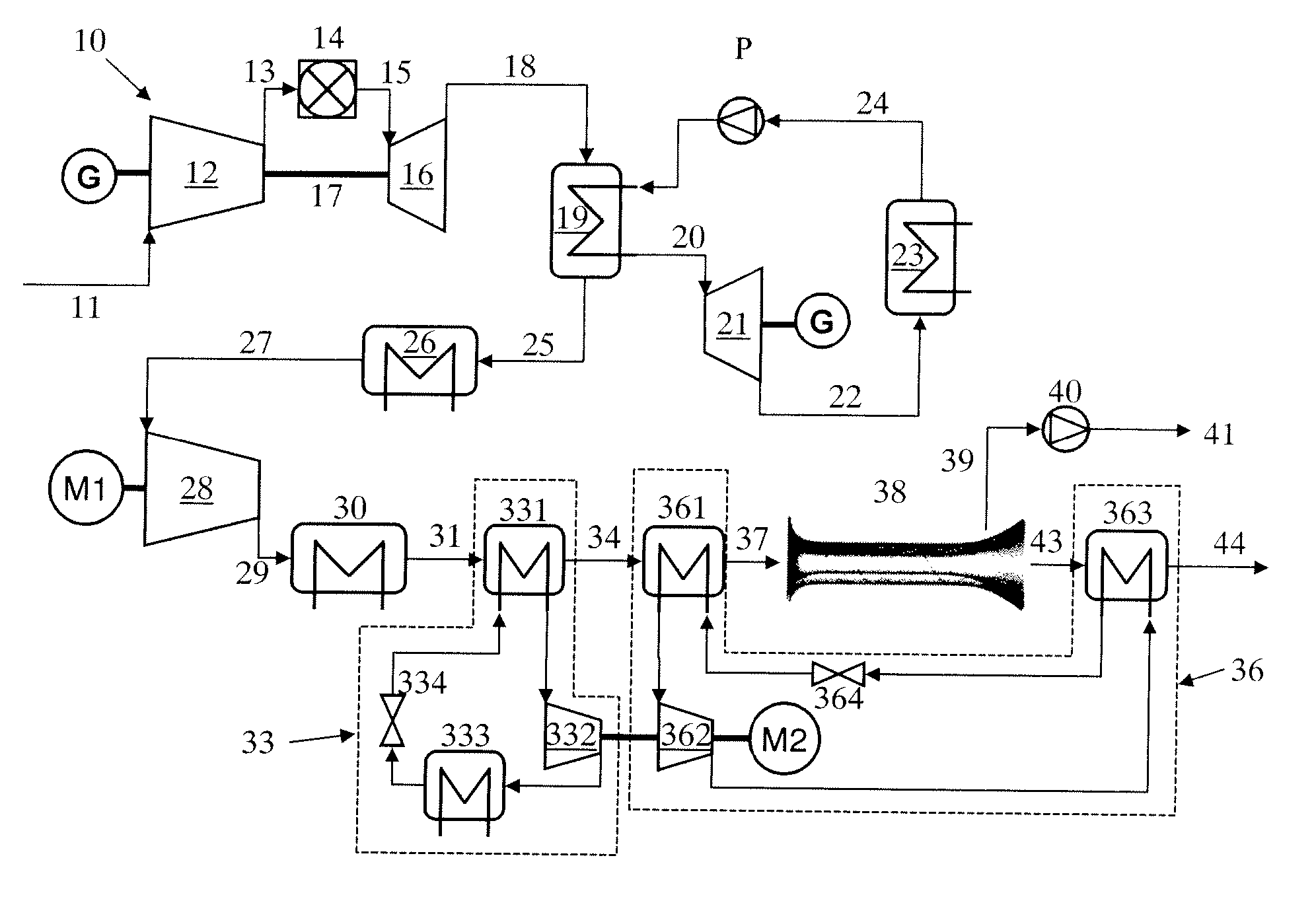
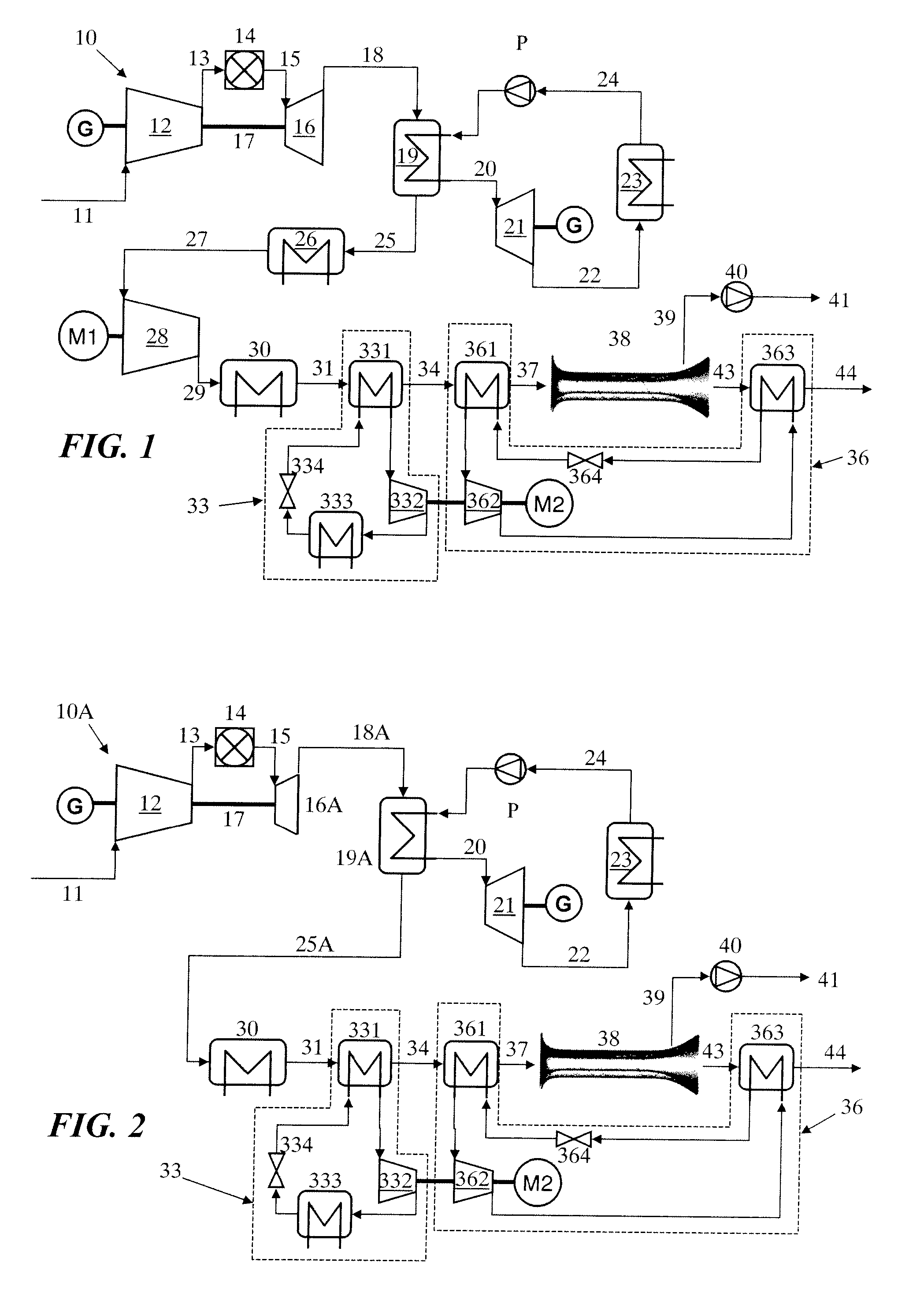
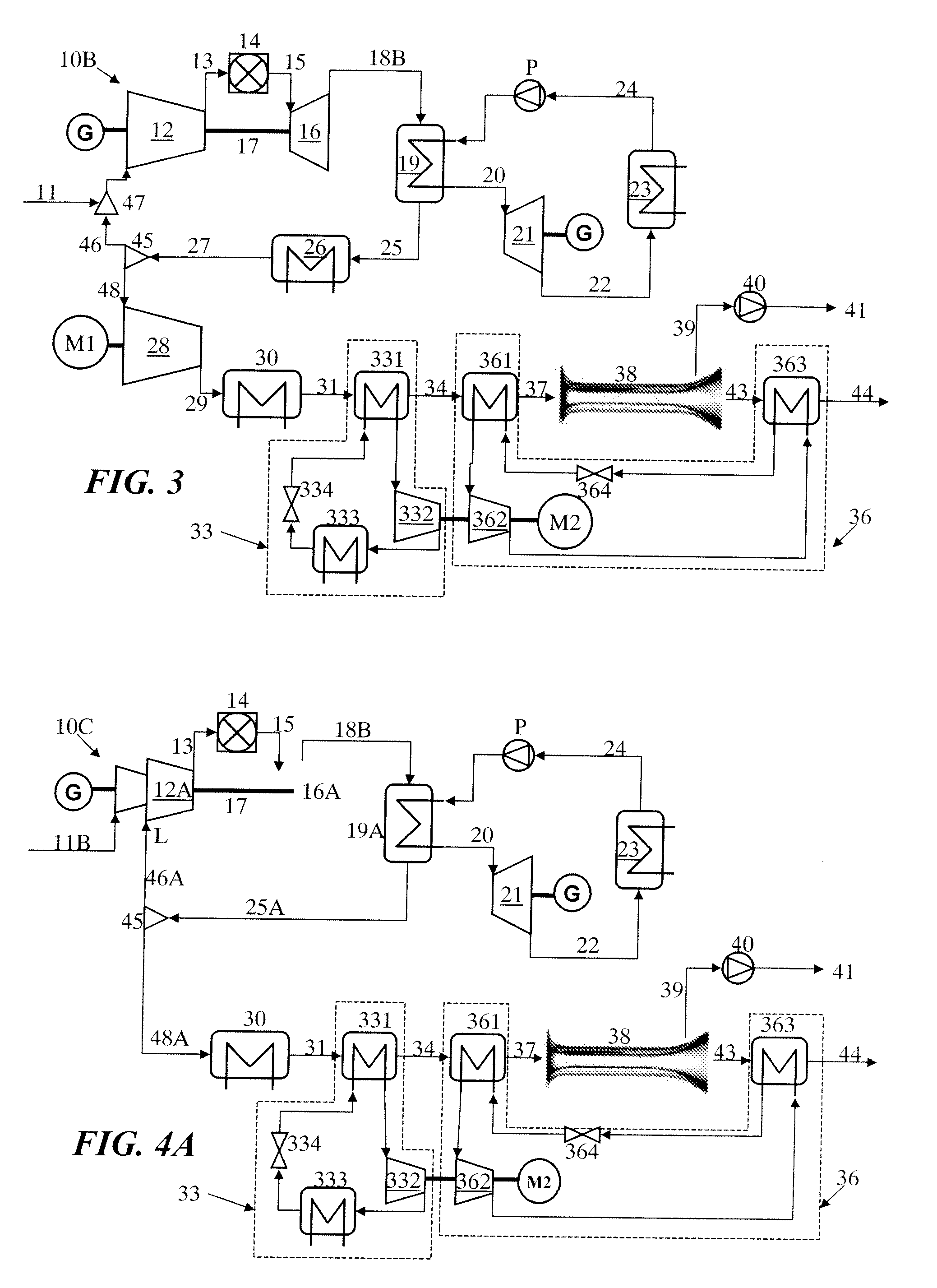
[0042]In FIGS. 1 to 4, plant components and fluid flows which are the same or closely similar in different Figures have been given the same reference numerals and will not be described again if they have been described for an earlier Figure.

[0043]Referring to FIG. 2 and comparing it with FIG. 1, it will be seen that the complexity of the plant has been reduced by omitting the gas cooler 26 and the compressor 28. This simplification is enabled by increasing the exhaust pressure of the turbine 16A of gas turbine engine 10A, compared with the original turbine 16 of gas turbine engine 10. Practically, this can be achieved by removing at least the last stage of the turbine 16. The number of turbine stages removed from turbine 16, to achieve the modified turbine 16A, will depending on the type of existing engine being considered for use in conjunction with embodiments adhering to principles of the present invention, but is likely to be one or two, and unlikely to be more than three stages...


PUM


Abstract

A low carbon emissions, combined cycle power plant utilizes vortex nozzles (38) operative at cryogenic temperatures to separate out carbon dioxide (39) from the flue gases. Complexity of the plant is minimized by operating a gas turbine engine component (10) of the plant at a turbine exhaust pressure of at least 2 bar, so that downstream components of the plant, including a heat recovery steam generator (19A), a gas cooling system (30, 33, 36), and the inlets of the vortex nozzles, all operate at the same pressure of at least two bar. To increase carbon dioxide concentration in the flue gases (37) that pass through the vortex nozzles (38), and thereby increase efficiency of carbon dioxide removal from the flue gases, up to 50% of the flue gases that exit the heat recovery steam generator (19A) may be recirculated to a location (L, FIG. 4)) in the compressor of the gas turbine engine where the pressure of the compressor air matches the flue gas pressure.

Description

[0001]This application is a Continuation of, and claims priority under 35 U.S.C. §120 to, International application number PCT / EP2009 / 050727, filed 22 Jan. 2009, and claims priority under 35 U.S.C. §119 therethrough to European application number 08101260.1, filed 4 Feb. 2008, the entireties of which are incorporated by reference herein.BACKGROUND[0002]1. Field of Endeavor[0003]The present invention relates to the field of climate protection technology, and in particular to reduced complexity and increased efficiency of carbon capture in combined cycle power plants, in which waste heat from a gas turbine engine is used to raise steam for a steam turbine.[0004]2. Brief Description of the Related Art[0005]Devices for production and separation of carbon dioxide (CO2) from gas streams, using cryogenic separation units in the form of vortex nozzles (also called cyclonic separators), are known from prior published patent applications WO-A2-03 / 029739 and US-A1-2003 / 0145724. To operate effi...

Claims


Application Information

Patent Timeline
Patent Type & Authority Applications(United States)
IPC IPC(8): F02C1/00F02C6/00
CPCB01D2257/504F01K23/10F02C3/34F05D2230/80Y02C10/12Y02E20/16F05D2230/50Y02C10/04Y02C20/40Y02E20/32
Inventor GUIDATI, GIANFRANCOPEDRETTI, CAMILLE
Owner GENERAL ELECTRIC TECH GMBH
Why Eureka
Try Eureka