Test apparatus for digital modulated signal

a digital modulated signal and test apparatus technology, applied in phase-modulated carrier systems, instruments, amplitude demodulation, etc., can solve the problems of ber (bit error rate) degradation, data rate acceleration also has a limit, and there is no known multi-channel test apparatus capable of testing such devices for mass production, so as to reduce the circuit scale

Active Publication Date: 2010-12-23
ADVANTEST CORP
View PDF3 Cites 97 Cited by
  • Summary
  • Abstract
  • Description
  • Claims
  • Application Information

AI Technical Summary

Benefits of technology

[0045]Such an arrangement is capable of controlling the phase difference between the in-phase detection signal and the qua

Problems solved by technology

However, the data rate acceleration also has a limit, leading to a problem of BER (Bit Error Rate) degradation due to high-frequency loss or reflection in the transmission line.
However, at the present time, there is no known multi-channel test apparatus which is capable of testing such devices for mass production.
However, each conventional wireless communication device has a single or several I/O (input/output) communication ports (

Method used


Image

  • Test apparatus for digital modulated signal
  • Test apparatus for digital modulated signal
  • Test apparatus for digital modulated signal

Examples


Embodiment Construction

[0061]Description will be made below regarding preferred embodiments according to the present invention with reference to the drawings. The same or similar components, members, and processes are denoted by the same reference numerals, and redundant description thereof will be omitted as appropriate. The embodiments have been described for exemplary purposes only, and are by no means intended to restrict the present invention. Also, it is not necessarily essential for the present invention that all the features or a combination thereof be provided as described in the embodiments.

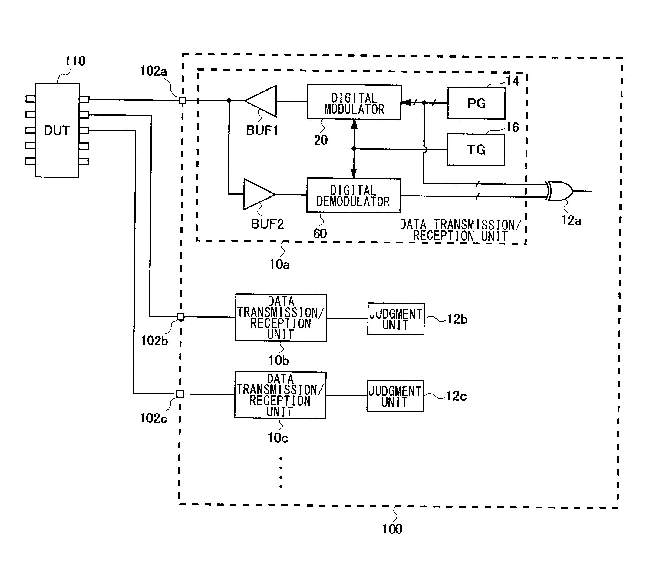
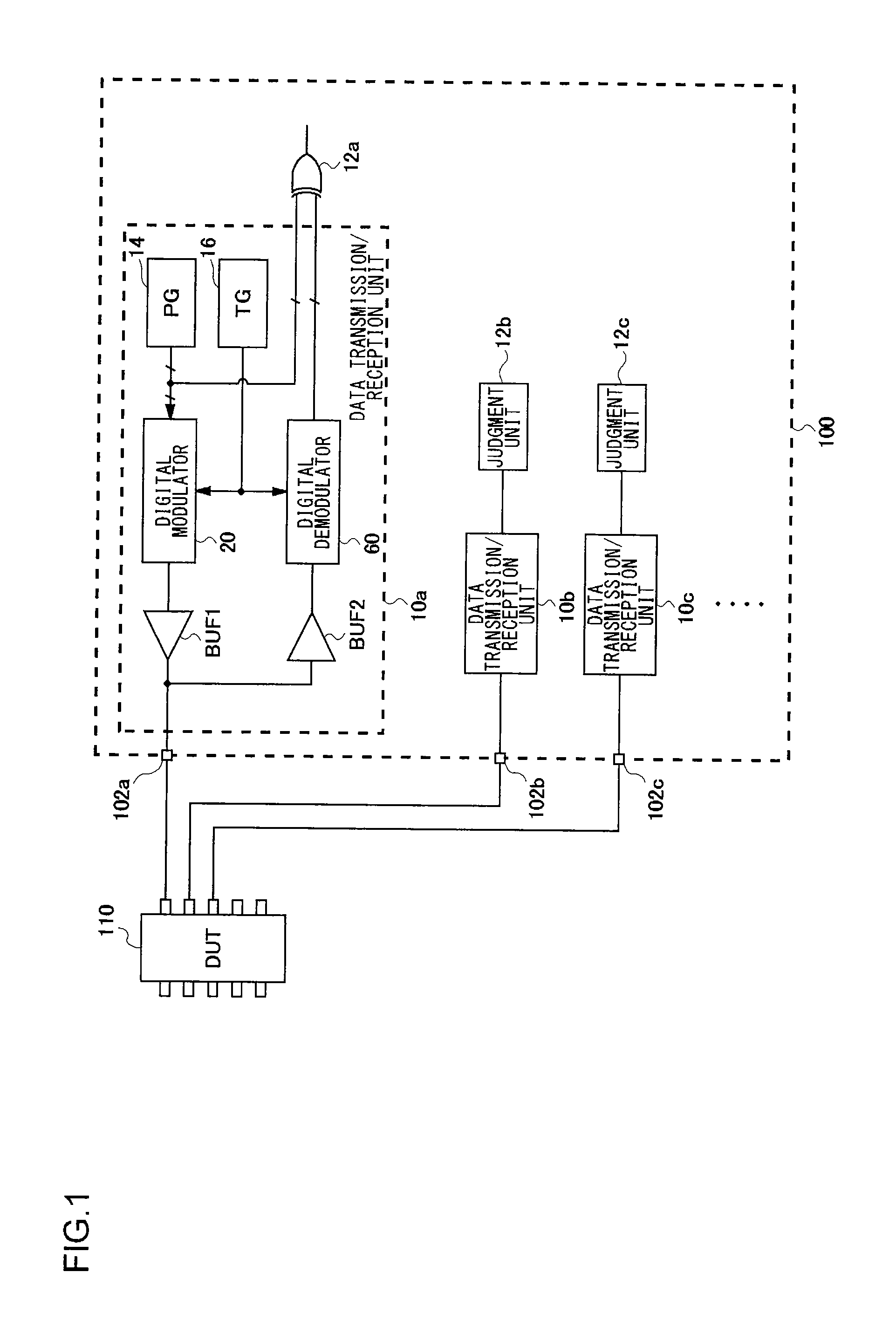
[0062]The test target to be tested by a test apparatus according to an embodiment is a device under test (DUT) including a transmission / reception interface for digitally multi-value modulated (which will simply be referred to as “digitally modulated” hereafter) digital data. That is to say, a pattern signal is digitally modulated, and the pattern signal thus digitally modulated is supplied to the DUT. Further...


PUM


Abstract

A test apparatus includes digital modulators provided in increments of multiple channels. A baseband signal generator performs retiming of data input as a modulation signal for the in-phase (quadrature) component, using a timing signal the timing of which can be adjusted, thereby generating a baseband signal. A driver generates a multi-value digital signal having a level that corresponds to the baseband signal output from the baseband signal generator. A multiplier amplitude-modulates a carrier signal with the multi-value digital signal. An adder sums the output signals of the multipliers.

Description

[0001]This application is the U.S. National Stage of International Patent Application No. PCT / JP2009 / 000747 filed on Feb. 20, 2009, and claims priority thereto, and further claims priority to Japanese Patent Application No. 2008-040378 filed on Feb. 21, 2008 the disclosures of which is hereby incorporated by reference in its entirety.1. FIELD OF THE INVENTION[0002]The present invention relates to a digital data transmission technique.2. DESCRIPTION OF THE RELATED ART[0003]In conventional digital wired communication, a binary transmission method using time division multiplexing (TDM) has been the mainstream. In this case, high-capacity transmission has been realized by parallel transmission or high-rate transmission. In order to overcome the physical limitations on parallel transmission, serial transmission, which is high-speed transmission, is performed at a data rate of several Gbps to 10 Gbps or more using a high-speed interface (I / F) circuit. However, the data rate acceleration a...

Claims


Application Information

Patent Timeline
IPC IPC(8): H03C1/00G06F19/00H03D1/00
CPCG01R31/31924H04L25/4917H04L27/38H04L27/362H04L27/34
Inventor WATANABE, DAISUKEOKAYASU, TOSHIYUKI
Owner ADVANTEST CORP
Why Eureka
Try Eureka