
Method for producing optical film, optical film, and image display

a technology of optical film and image display, applied in the direction of instruments, polarising elements, coatings, etc., can solve the problems of low productivity, high frequency of productivity is further decreased, so as to achieve the effect of increasing productivity, reducing application defects and foreign matter trapped in the film

Inactive Publication Date: 2010-12-23
NITTO DENKO CORP
View PDF14 Cites 7 Cited by
  • Summary
  • Abstract
  • Description
  • Claims
  • Application Information

AI Technical Summary

Benefits of technology

[0006]The aforementioned producing method requires a large number of steps such as a step of producing a resin film, a step of applying a pressure sensitive adhesive agent on a shrinkable film, a step of attaching the resin film and the shrinkable film, a step of stretching and shrinking, and a step of removing the shrinkable film, and has low productivity. Further, in the aforementioned producing method, application defects are caused and foreign matters are trapped with high frequency in the step of attaching and productivity is further decreased. Moreover, in the aforementioned producing method, adhesive deposits are generated in the step of removing, and productivity is further decreased. In the aforementioned producing method, alignment defects are caused due to defects in adhesive property such as nonuniformity of adhesive force and flaking, and the quality of the optical film is decreased.
[0007]The present invention is intended to provide a method for producing an optical film including a birefringent layer having a refractive index distribution satisfying nx>nz>ny that can be produced by a small number of steps, contains less foreign matter trapped therein, and has high productivity.
[0009]In the method for producing an optical film of the present invention, a material for forming a birefringent layer is directly applied on a shrinkable film without using a pressure sensitive adhesive agent or the like. Therefore, according to the present invention, a step of attaching a resin film and a shrinkable film that is conducted in a conventional method can be omitted and productivity is increased. Further, according to the present invention, since the step of attaching can be omitted, application defects and foreign matters trapped therein can be reduced, and productivity is further increased. Since alignment defects due to defects in adhesive property are not caused, the present invention provides an optical film of high quality. Moreover, since the number of steps and foreign matters trapped therein can be reduced, the present invention brings about an adventitious effect that an optical film with high alignment axis accuracy can be obtained.

Problems solved by technology

The aforementioned producing method requires a large number of steps such as a step of producing a resin film, a step of applying a pressure sensitive adhesive agent on a shrinkable film, a step of attaching the resin film and the shrinkable film, a step of stretching and shrinking, and a step of removing the shrinkable film, and has low productivity.
Further, in the aforementioned producing method, application defects are caused and foreign matters are trapped with high frequency in the step of attaching and productivity is further decreased.
Moreover, in the aforementioned producing method, adhesive deposits are generated in the step of removing, and productivity is further decreased.
In the aforementioned producing method, alignment defects are caused due to defects in adhesive property such as nonuniformity of adhesive force and flaking, and the quality of the optical film is decreased.

Method used


Image

  • Method for producing optical film, optical film, and image display
  • Method for producing optical film, optical film, and image display
  • Method for producing optical film, optical film, and image display

Examples


example 1

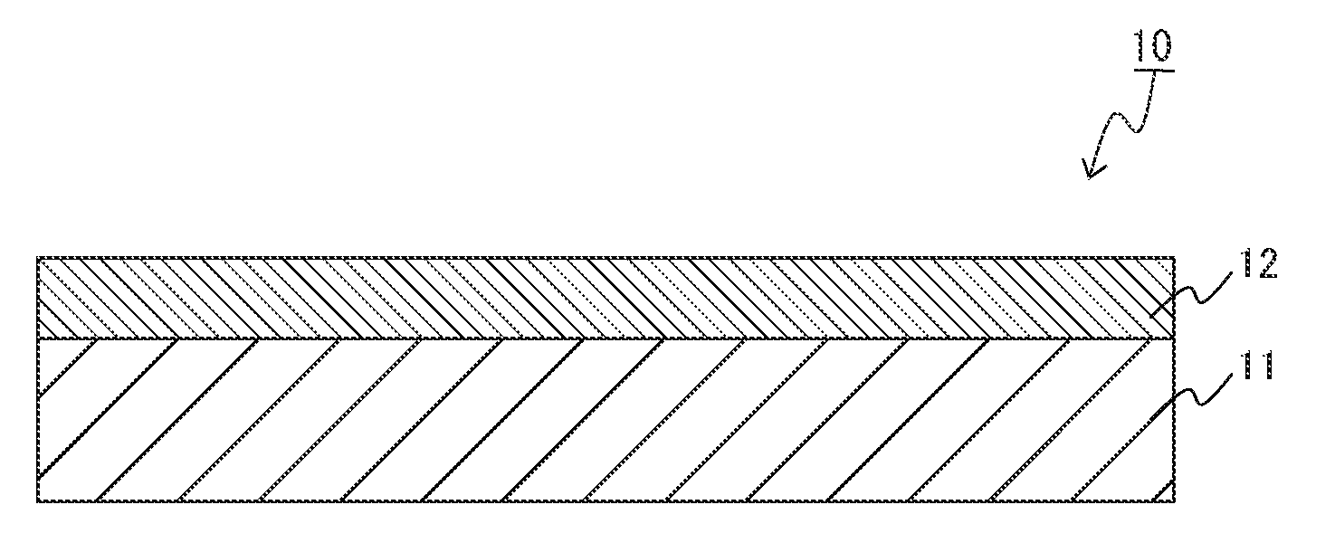
[0071]A material for forming a birefringent layer was prepared by dissolving a norbornene resin (10 g) to toluene (73 g). Next, a coating film was formed by directly applying the material for forming a birefringent layer on a shrinkable film (uniaxially-stretched film of an acrylic resin, 500 mm×200 mm, thickness of 93 μm) using a wire bar. Then, the coating film was dried at 110° C. for 5 minutes to produce a laminate of the shrinkable film and the coating film. Thereafter, using a batch-type simultaneous biaxial stretching machine, at 140° C., the coating film was shrunk by shrinking the laminate 0.8-fold, at the same time, the laminate was stretched 1.5-fold in a direction orthogonal to the shrinking direction of the coating film. Then, the birefringent layer was removed from the shrinkable film. The thickness of the birefringent layer was 130 μm, nx=1.521, ny=1.519, and nz=1.520. In this manner, the optical film of Example 1 was obtained.

example 2

[0072]A material for forming a birefringent layer was prepared by dissolving a polycarbonate resin (10 g) to methylene chloride (73 g). Next, a coating film was formed by directly applying the material for forming a birefringent layer on a shrinkable film (biaxially-stretched film of PP, 500 mm×200 mm, thickness of 60 μm) using a wire bar. Then, the coating film was dried at 60° C. for 5 minutes to produce a laminate of the shrinkable film and the coating film. Thereafter, using a batch-type simultaneous biaxial stretching machine, at 150° C., the coating film was shrunk by shrinking the laminate 0.9-fold, at the same time, the laminate was stretched 1.4-fold in a direction orthogonal to the shrinking direction of the coating film. Then, the birefringent layer was removed from the shrinkable film. The thickness of the birefringent layer was 60 μm, nx=1.589, ny=1.581, and nz=1.585. In this manner, the optical film of Example 2 was obtained.

example 3

[0073]A material for forming a birefringent layer was prepared by dissolving a cellulose acetate resin (10 g) to methylene chloride (73 g). Next, a coating film was formed by directly applying the material for forming a birefringent layer on a shrinkable film (biaxially-stretched film of PP, 500 mm×200 mm, thickness of 60 μm) using a wire bar. Then, the coating film was dried at 60° C. for 5 minutes to produce a laminate of the shrinkable film and the coating film. Thereafter, using a batch-type simultaneous biaxial stretching machine, at 120° C., the coating film was shrunk by shrinking the laminate 0.7-fold, at the same time, the laminate was stretched 2.0-fold in a direction orthogonal to the shrinking direction of the coating film. Then, the birefringent layer was removed from the shrinkable film. The thickness of the birefringent layer was 50 μm, nx=1.504, ny=1.496, and nz=1.501. In this manner, the optical film of Example 3 was obtained.


PUM

PropertyMeasurementUnit
thicknessaaaaaaaaaa
thicknessaaaaaaaaaa
Tgaaaaaaaaaa

Abstract

A method for producing an optical film including a birefringent layer having a refractive index distribution satisfying nx>nz>ny that can be produced by a small number of steps, contains less foreign matter trapped therein, and has high productivity.An optical film including a birefringent layer, wherein the method includes steps of: forming a coating film by directly applying a material for forming a birefringent layer on the shrinkable film; shrinking the coating film in a first direction by shrinking the shrinkable film; and stretching a laminate of the shrinkable film and the coating film in a second direction orthogonal to the first direction, wherein the material for forming a birefringent layer contains at least one resin selected from the group consisting of norbornene resins, polycarbonate resins, cellulose resins, polyamides, and polyurethanes, and wherein the birefringent layer has a refractive index distribution satisfying nx>nz>ny.

Description

CROSS-REFERENCE TO RELATED APPLICATION[0001]This application claims priority from Japanese Patent Application Nos. 2009-146328 filed on Jun. 19, 2009 and 2010-076119 filed on Mar. 29, 2010. The entire subject matter of the Japanese Patent Applications are incorporated herein by reference.BACKGROUND OF THE INVENTION[0002]1. Field of the Invention[0003]The present invention relates to a method for producing an optical film, an optical film, and an image display.[0004]2. Description of Related Art[0005]For various image displays such as a mobile phone, a PC monitor, a liquid crystal television, and the like, liquid crystal displays (LCDs) with high contrast utilizing birefringence are used. In these years, definition of LCDs is getting higher and the application thereof covers a broad spectrum, so that improvement of display qualities of LCDs such as increase in a viewing angle, and the like is required. For the increase in a viewing angle, for example, an optical film having a refract...

Claims


Application Information

Patent Timeline
Patent Type & Authority Applications(United States)
IPC IPC(8): G02B5/30B05D5/06B05D7/04G02F1/13363
CPCG02F1/133634G02B5/3083
Inventor KAWASAKI, MOTOKOIIDA, TOSHIYUKIMURAKAMI, NAOYOSHIMI, HIROYUKI
Owner NITTO DENKO CORP
Features
  • Generate Ideas
  • Intellectual Property
  • Life Sciences
  • Materials
  • Tech Scout
  • Unparalleled Data Quality
  • Higher Quality Content
  • 60% Fewer Hallucinations
Learn More