
Multilayer overlays and methods for applying multilayer overlays

Inactive Publication Date: 2010-12-23
EXTREME SURFACE PROTECTION
View PDF70 Cites 23 Cited by
  • Summary
  • Abstract
  • Description
  • Claims
  • Application Information

AI Technical Summary

Benefits of technology

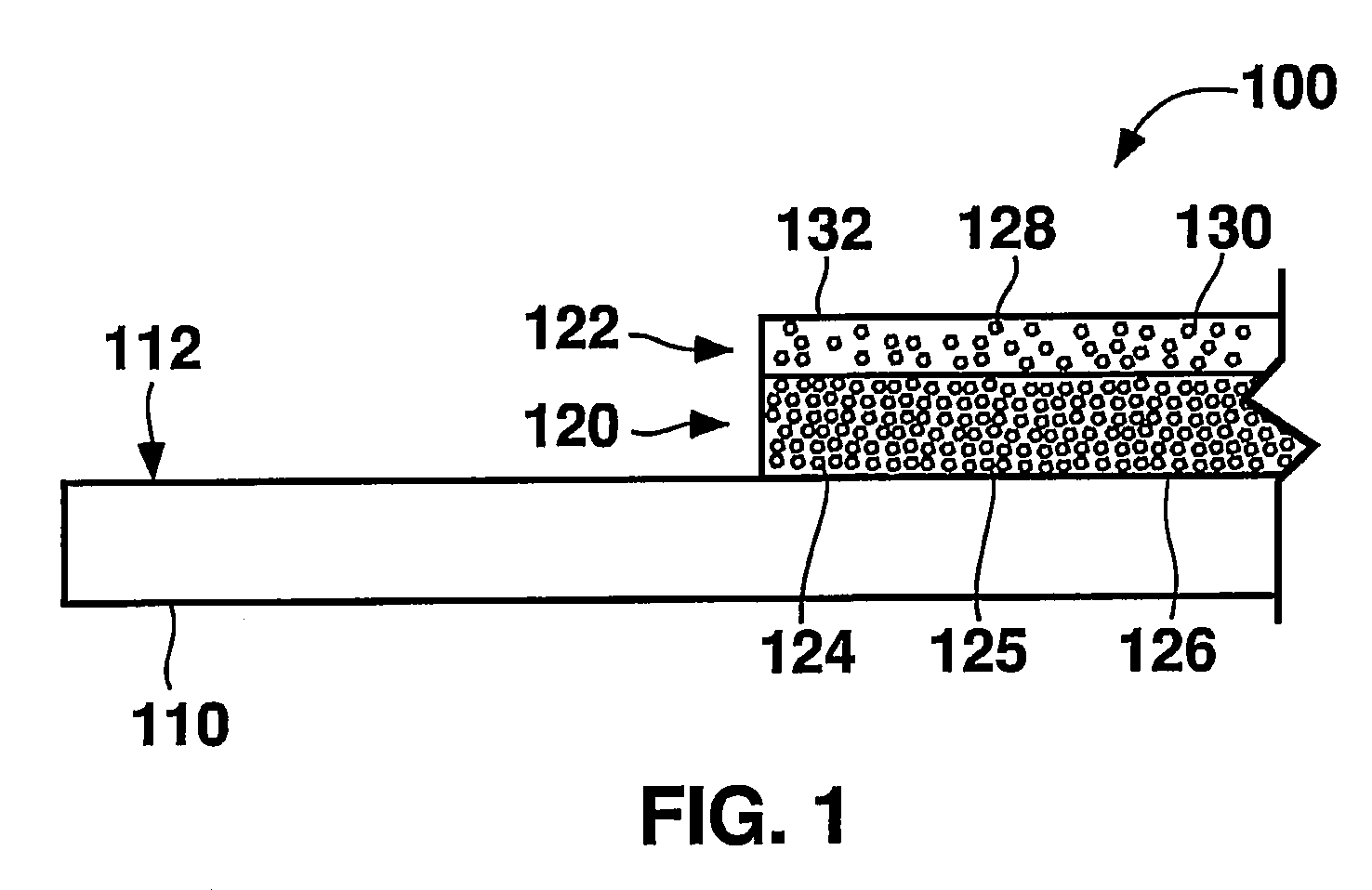
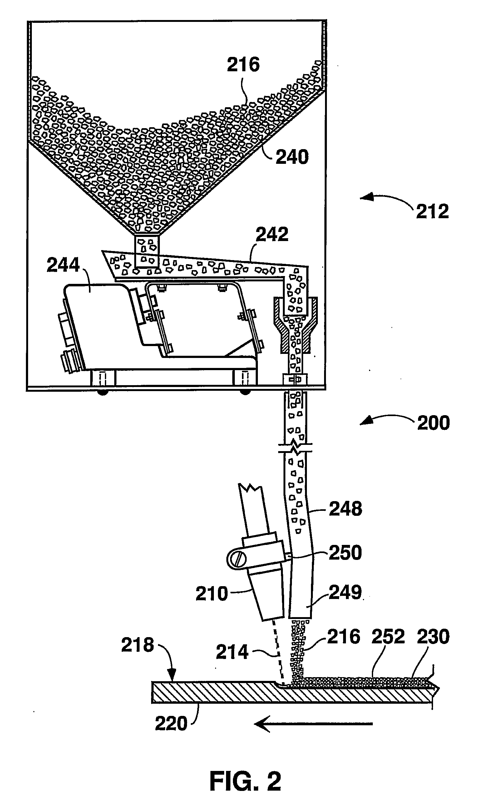
[0014]An additional non-limiting aspect according to the present disclosure is directed to a method of improving the resistance of a metallic surface to at least one of erosion, corrosion, and abrasion by providing a wear resistant multilayer overlay according to the present disclosure on at least a region of the metallic surface. The method includes providing a first or inner layer on at least a region of the metallic surface, and providing a second or outer layer metallurgically bonded to at least a region of the first or inner layer. The first or inner layer comprises at least one of first hard particles, blocky diamond particles, non-blocky diamond particles, TSP diamond, cubic boron nitride particles, and PCD compacts dispersed and embedded in a first continuous metallic matrix, wherein the first hard particles are at least one of transition metal carbide particles and boron nitride particles. The second or outer layer includes at least one of second hard particles, blocky diamond particles, non-blocky diamond particles, TSP diamond, cubic boron nitride particles, and PCD compacts dispersed and embedded in the second continuous metallic matrix. The second hard particles are at least one of transition metal carbide particles and boron nitride particles.

Problems solved by technology

The conditions promoting wear of such parts can be abrasive, erosive, and / or chemical in nature, and can be extremely aggressive.
The nature of material flow parts, for example, often makes servicing and replacing them difficult, and the process downtime and man-hours associated with repairing or replacing parts in these systems can be very costly.
Although many additional attempts to produce diamond in the laboratory were made over the years, it is believed that until the 1950s those attempts were unsuccessful given the intrinsic difficulty of replicating the conditions under which diamond forms naturally.
First, extremely high pressure is needed to achieve the compact, strongly bonded structure of diamond.
Third, even when the pressure and temperature conditions are achieved, only very small diamond grains are produced.
By 1941, the General Electric, Carborundum, and Norton companies and P.S. Bridgeman, a well known researcher in the field of high pressure, agreed to jointly investigate diamond synthesis, but the effort was discontinued prematurely due to the war.

Method used


Image

  • Multilayer overlays and methods for applying multilayer overlays
  • Multilayer overlays and methods for applying multilayer overlays
  • Multilayer overlays and methods for applying multilayer overlays

Examples


Embodiment Construction

[0021]In the present description of non-limiting embodiments, other than in the operating examples or where otherwise indicated, all numbers expressing quantities or characteristics of ingredients and products, processing conditions, and the like are to be understood as being modified in all instances by the term “about”. Accordingly, unless indicated to the contrary, any numerical parameters set forth in the following description are approximations that may vary depending upon the desired properties one seeks to obtain in the present invention. At the very least, and not as an attempt to limit the application of the doctrine of equivalents to the scope of the claims, each numerical parameter should at least be construed in light of the number of reported significant digits and by applying ordinary rounding techniques.

[0022]Any patent, publication, or other disclosure material, in whole or in part, that is said to be incorporated by reference herein is incorporated herein only to th...


PUM

PropertyMeasurementUnit
Lengthaaaaaaaaaa
Thicknessaaaaaaaaaa
Thicknessaaaaaaaaaa

Abstract

A wear resistant multilayer overlay includes a first layer on at least a surface of an article, and a second layer metallurgically bonded to at least a portion of the first layer. The first layer includes a first continuous metallic matrix and at least one of first hard particles, blocky diamond particles, non-blocky diamond particles, TSP diamond, cubic boron nitride particles, and PCD compacts embedded in the first continuous metallic matrix, wherein the first hard particles are at least one of transition metal carbide particles and boron nitride particles. The second layer includes a second continuous metallic matrix and at least one of second hard particles, blocky diamond particles, non-blocky diamond particles, TSP diamond, cubic boron nitride particles, and PCD compacts, embedded in the second continuous metallic matrix, wherein the second hard particles are at least one of transition metal carbide particles and boron nitride particles. Related methods and articles of manufacture also are disclosed.

Description

BACKGROUND OF THE TECHNOLOGY[0001]1. Field of Technology[0002]The present disclosure relates to multilayer overlays providing corrosion, erosion and / or abrasion resistance to surfaces of articles of manufacture. The present disclosure also relates to methods for applying multilayer overlays to article surfaces, wherein the overlays provide resistance to corrosion, erosion, and / or abrasion.[0003]2. Description of the Background of the Technology[0004]For many years, attempts have been made to reduce wear experienced by pipes, valves, gaskets, and other material flow parts in energy systems, refineries, coke plants, and chemical production facilities, as well as by components that handle or contact abrasive materials. Examples of such parts include pipe, valves, and other parts subjected to a flow of highly abrasive oil sands in energy production systems, or subjected to a flow of highly corrosive chemicals in chemical production plants. Other examples of such parts include excavating...

Claims


Application Information

Patent Timeline
IPC IPC(8): F16L9/14B32B15/18B32B15/04B32B15/00B23K31/02B23K9/173B23K9/167B23K9/00
CPCB22F5/10Y10T428/12076B23K9/042B23K9/167B23K9/173B23K35/0261B23K35/3033B23K35/3053B23K35/308B23K2201/18B23K2201/34B23K2203/04B23K2203/08B32B15/01C22C26/00C23C28/027F16L9/14F16L57/06C23C28/021C23C28/023Y10T428/12493Y10T428/12056B22F7/08B23K2103/05B23K2103/26B23K2101/18B23K2101/34B23K2103/04B23K2103/08Y10T428/12639B32B15/043B32B2264/108
Inventor AITCHISON, TREVORHEFLIN, R. ALLAN
Owner EXTREME SURFACE PROTECTION
Learn More