Hydraulic power transmission system for a mineral material processing plant, a method for controlling the same, a screening machine and a crushing machine

Inactive Publication Date: 2010-12-30
METSO MINERALS INC
View PDF7 Cites 12 Cited by
  • Summary
  • Abstract
  • Description
  • Claims
  • Application Information

AI Technical Summary

Benefits of technology

[0046]Thanks to the invention, significant power savings are achieved, as the pressure differences between the conveyors can be kept small and the volume flows are reduced. The diesel engine power saved in this way can be utilized elsewhere in the apparatus. In the case of a screening machine or a crusher, the saved power can be used, for example, in a crusher connected to a screening machine, wherein its crushing result is improved. Furthermore, it is unnecessary to overdimension the components, for example the hydraulic pump or even the diesel engine.
[0047]Moreover, the fuel consumption of

Problems solved by technology

A problem with conventional screening machines is that the rotation speeds of the drawing drums of all the product type conveyors are adjusted according to the maximum load of the conveyors.
However, in a practical use situation, all the conveyors are seldom, if ever, charged with the maximum load of material to be transferred simultaneously.
This means that at least some of the conveyors rotate at a speed that is too high with respect to the conveying need.
Such a conveyor rotating at too high a speed and charged with only a small load is also operated at too low a pressure level compared with the pressure level of the conveyors rotating simultaneously at a heavy load.
Such pressure differences cause power losses in the load sensing system.
The power losses increase the diesel fuel cons

Method used


Image

  • Hydraulic power transmission system for a mineral material processing plant, a method for controlling the same, a screening machine and a crushing machine
  • Hydraulic power transmission system for a mineral material processing plant, a method for controlling the same, a screening machine and a crushing machine
  • Hydraulic power transmission system for a mineral material processing plant, a method for controlling the same, a screening machine and a crushing machine

Examples


Embodiment Construction

[0056]FIGS. 1 to 4 were already described above, for which reason they will not be discussed any more in this context.

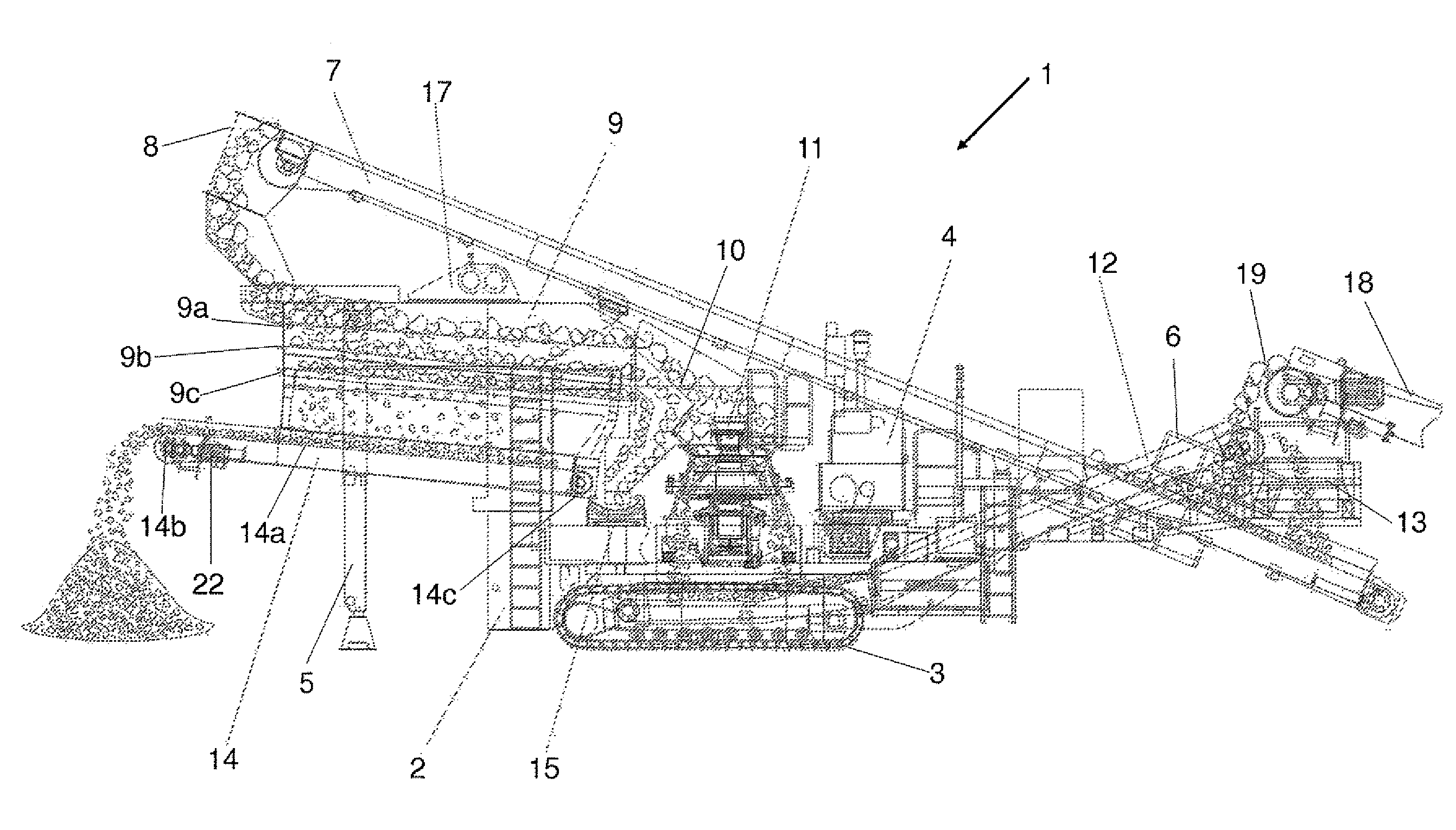
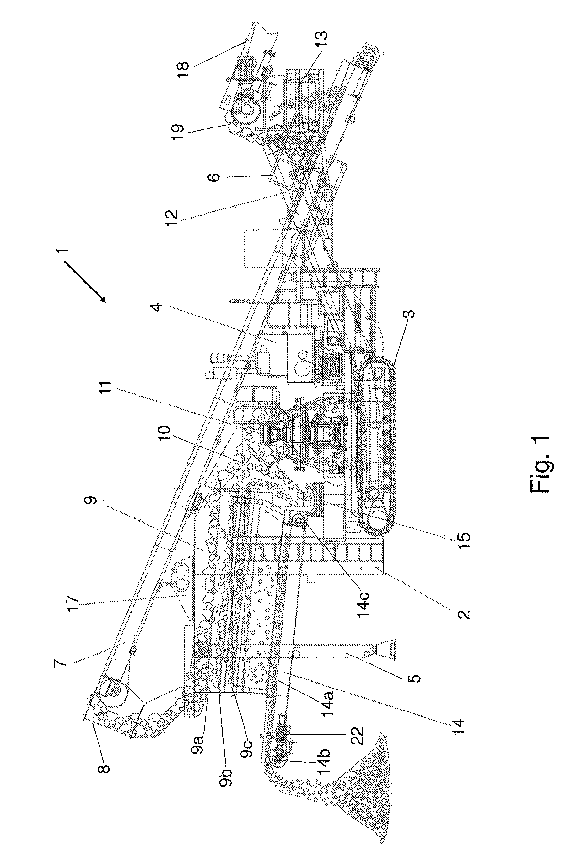
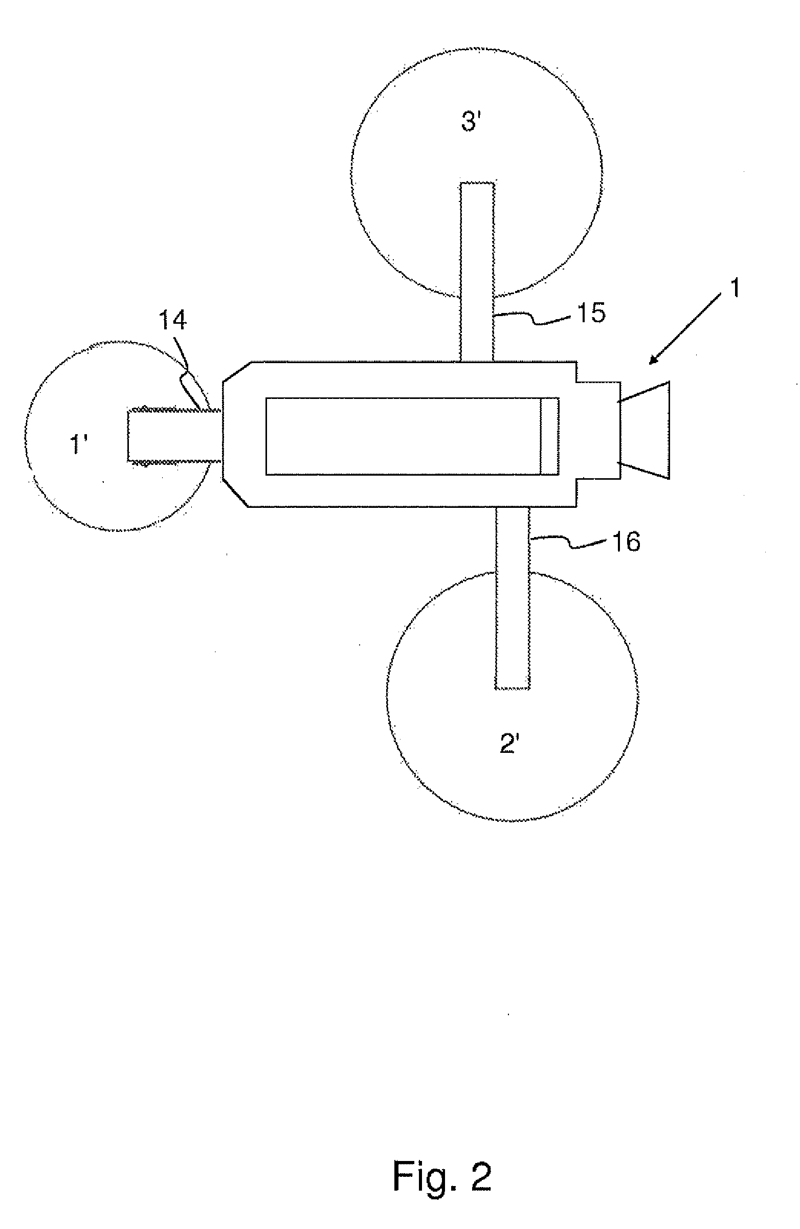
[0057]FIG. 5 shows a hydraulic transmission system 100 according to the invention. This embodiment shows a hydraulic transmission system for a processing plant, to which several conveyors are connected, the quantity of the material flow conveyed on the conveyors varying. The screening and / or crushing device and the other partial processes connected to it are substantially similar to those in the transmission system of prior art presented in connection with FIG. 4. The system according to this embodiment can be applied, for example, in a screening machine shown in FIGS. 1 and 2 or in a crushing machine shown in FIG. 3. The system is a load sensing system, to which four first motors 22-25 are connected, each driving the drawing drums of different conveyors of the processing plant. The system comprises parts that are similar to those in the system of prior art described...


PUM


Abstract

Hydraulic transmission system for a mineral material processing plant, which transmission system comprises at least two hydraulic first motors, which are arranged to drive at least one conveyor belonging to the mineral material processing plant, at least two first directional valves connected via the first actuator channels of the directional valves to each of the first motors, a hydraulic pump arranged to transfer hydraulic fluid via the first actuator channels of the directional valves to the first motors. The system also comprises pressure sensors. The first directional valves are valves that can be adjusted by external control during the running of the processing plant and which are arranged to control the volume flow of the hydraulic fluid supplied into the first motors. The control is made on the basis of the pressure of hydraulic fluid measured by pressure sensors in the first actuator channels the directional valves.

Description

FIELD OF THE INVENTION[0001]The invention relates to a hydraulic transmission system for a mineral material processing plant according to the preamble of the appended claim 1. The invention also relates to a method for controlling a hydraulic transmission system for a mineral material processing plant according to the preamble of the appended claim 16, as well as to a screening machine according to the preamble of the appended claims 31 and a crushing machine according to the preamble of the appended claim 39.BACKGROUND OF THE INVENTION[0002]The invention relates to a mineral material processing plant. In this description and the claims, a processing plant refers to any processing plant suitable for the processing of mineral materials, such as a crushing, screening or feeding machine, or a corresponding material transferring, refining or sorting device. Processing plants used for the recycling of material, such as shredders and metal separators, belong to this group as well. The mat...

Claims


Application Information

Patent Timeline
IPC IPC(8): F15B11/05F15B11/16B02C25/00B02C23/02
CPCB07B1/005B07B2201/04F15B11/165F15B2211/6313F15B2211/30535F15B2211/6054F15B2211/253
Inventor PERMI, SAMIKUJALA, TONIPELTONEN, MIKA
Owner METSO MINERALS INC
Why Eureka
Try Eureka