Cooling circuit for removing waste heat from an electromechanical converter and power generating plant with a cooling circuit of this type

a technology of electromechanical converter and waste heat removal, which is applied in the field of cooling circuit, can solve the problems of limiting the increase in output, gas turbine power generating plants sometimes already failing to meet the planned requirements, and reducing the cooling capacity of generators, so as to reduce the copper temperature of generators, reduce the temperature of chilling medium, and increase the cooling capacity

Inactive Publication Date: 2010-12-30
SIEMENS AG
View PDF11 Cites 3 Cited by
  • Summary
  • Abstract
  • Description
  • Claims
  • Application Information

AI Technical Summary

Benefits of technology

[0012]A power generating plant according to the invention comprises a turbine, in particular a gas turbine, a generator and a cooling circuit according to the invention for removing waste heat from the generator. The cooling circuit according to the invention thereby makes it possible to lower the temperature of the chilling medium flowing into the generator for cooling the generator and so increases the cooling capacity. As a result, the copper temperature of the generator can be lowered further.
[0013]The reduction in the copper temperature of the generator that can be achieved with the invention makes it possible to retrofit a gas turbine plant to increase the power output, the copper temperature having less of a limiting effect than without the cooling circuit according to the invention. Furthermore, the retrofitting does not require any intervention in the gas turbine process, such as would be necessary if the heat for driving the absorption chiller were extracted from the compressor air, or at least reduced intervention. Although, as likewise described in US 2008 / 0178590 A1, the heat for driving the absorption chiller may also be extracted from the exhaust gas of the gas turbine, this could also influence process parameters, for example if the gas turbine were operated in combination with a steam turbine in which the waste heat from the gas turbine is used for driving the steam turbine. By contrast with this, in the present invention heat which would otherwise be uselessly lost is at least for the most part used for driving the absorption chiller, and therefore does not lead to a change in a process parameter of the power generating plant or to a reduction in the useful output.

Problems solved by technology

The energy market today is growing so rapidly that, for example, gas turbine power generating plants sometimes already fail to satisfy the planned requirement on the day they are delivered.
However, the increases in output must be adapted to the component of the lowest design rating, i.e. the component allowing the lowest increase in output, with the result that this component restricts the increase in output that is possible in a gas turbine power generating plant by retrofitting.
An extraction of electrical energy from the generator for driving a mechanical compressor reduces the possible useful output of the generator.

Method used


Image

  • Cooling circuit for removing waste heat from an electromechanical converter and power generating plant with a cooling circuit of this type
  • Cooling circuit for removing waste heat from an electromechanical converter and power generating plant with a cooling circuit of this type
  • Cooling circuit for removing waste heat from an electromechanical converter and power generating plant with a cooling circuit of this type

Examples


Embodiment Construction

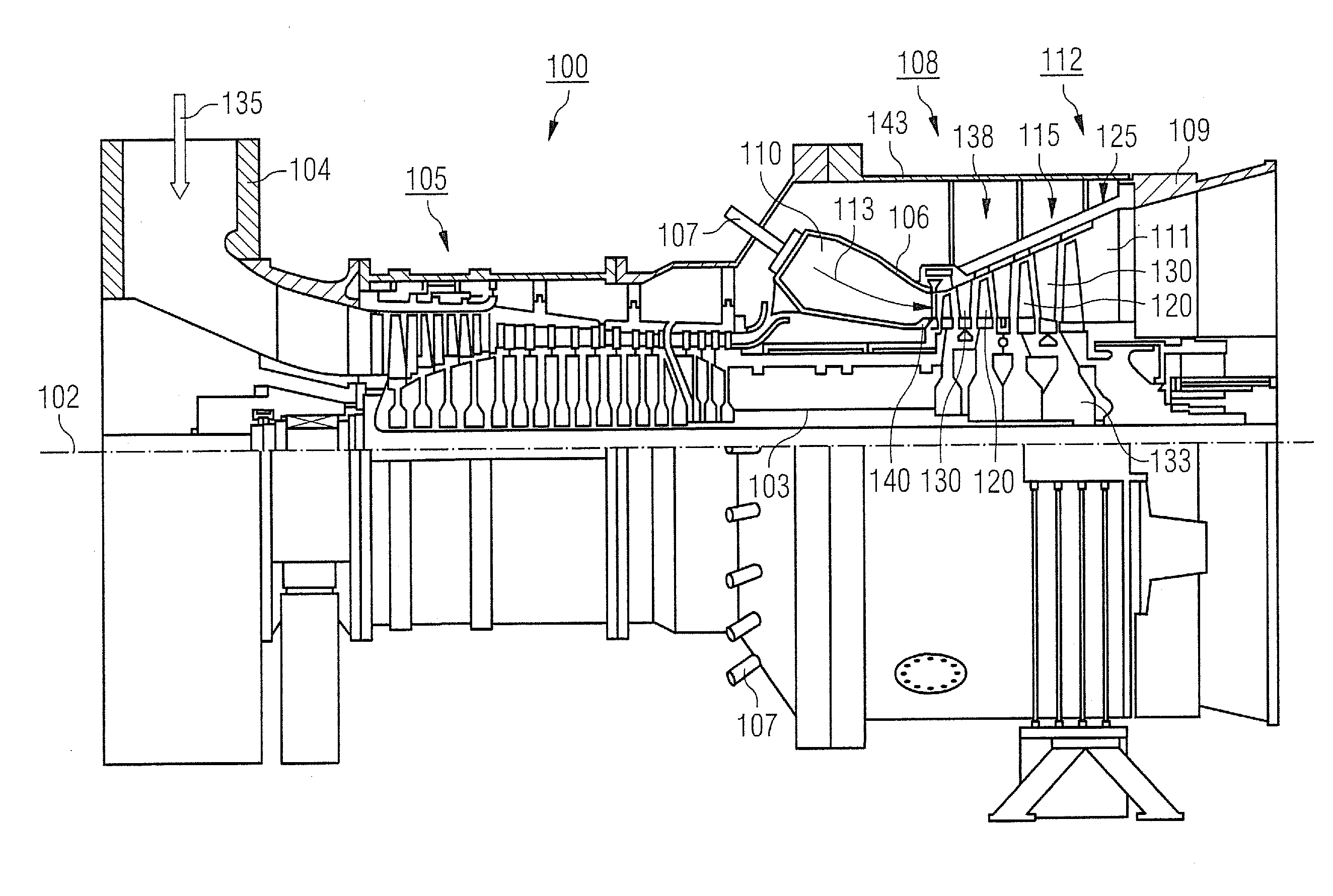
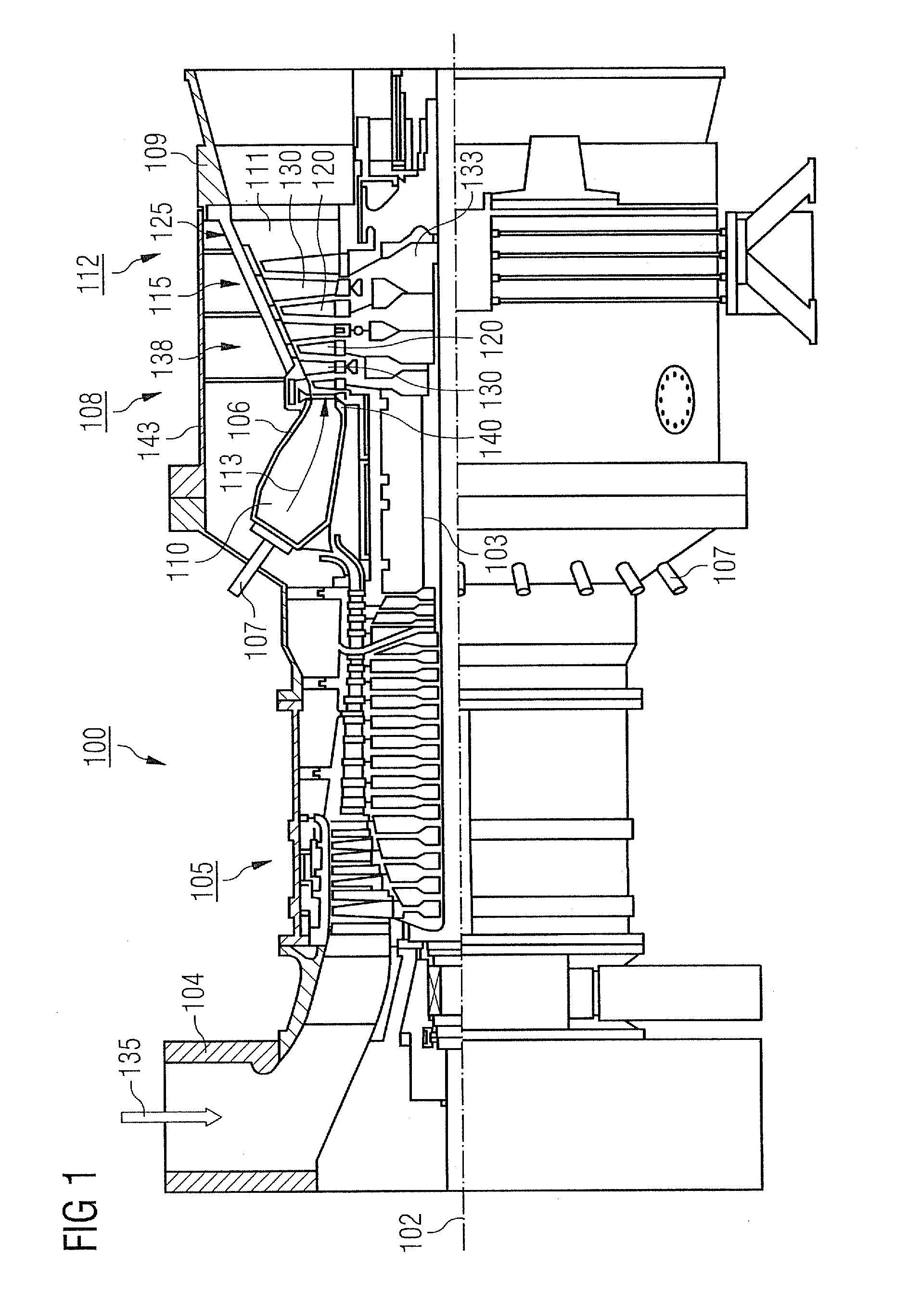
[0019]FIG. 1 shows by way of example a gas turbine 100 in a longitudinal partial section.

[0020]The gas turbine 100 has in the interior a rotor 103, which is rotatably mounted about an axis of rotation 102, has a shaft 101 and is also referred to as a turbine runner.

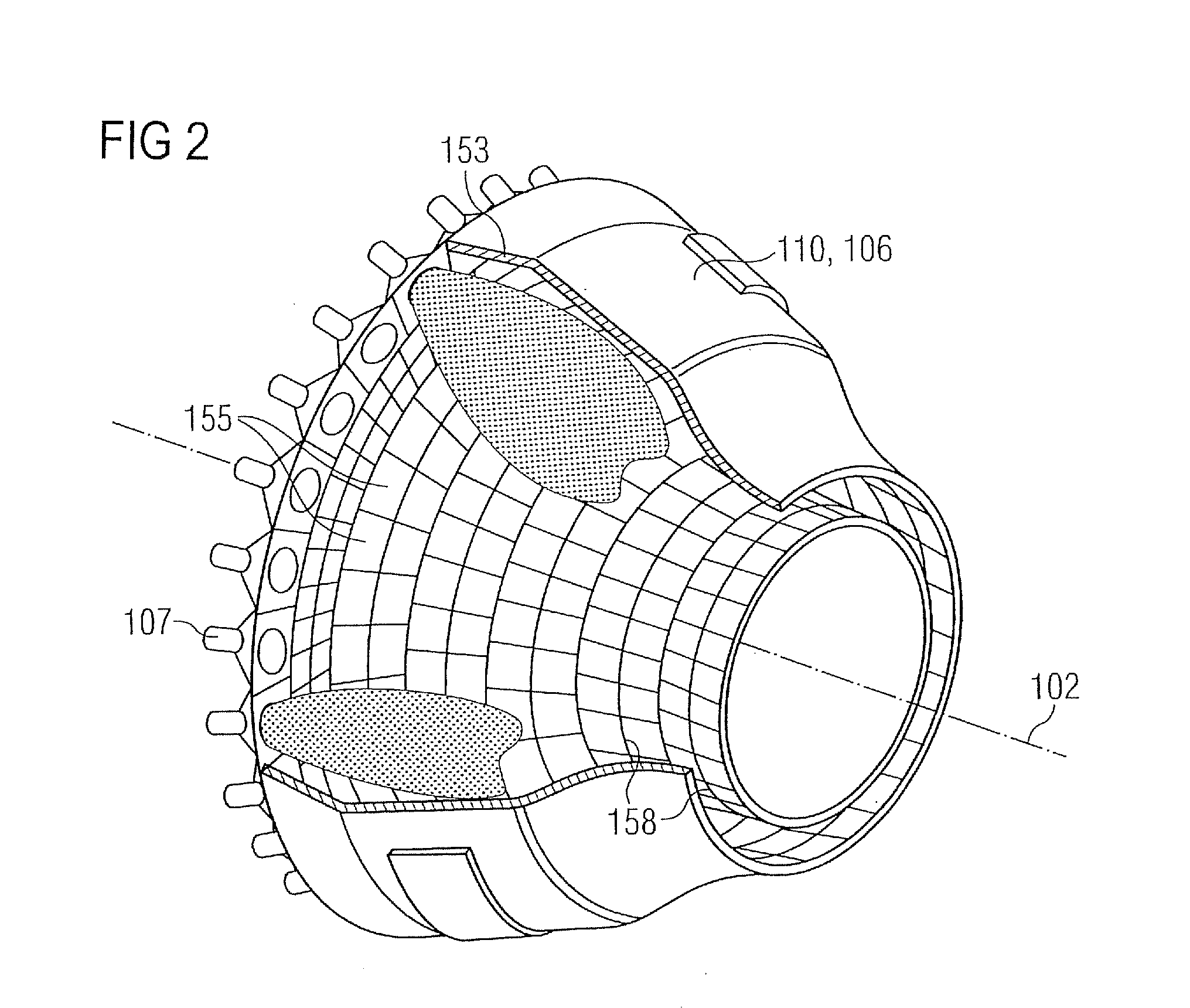
[0021]Following one another along the rotor 103 are an intake housing 104, a compressor 105, a combustion chamber 110, for example of a toroidal form, in particular an annular combustion chamber, with a number of coaxially arranged burners 107, a turbine 108 and the exhaust housing 109.

[0022]The annular combustion chamber 110 communicates with a hot gas duct 111, for example of an annular form. There, the turbine 108 is formed for example by four successive turbine stages 112.

[0023]Each turbine stage 112 is formed for example by two blade rings. As seen in the direction of flow of a working medium 113, a row of stationary blades 115 is followed in the hot gas duct 111 by a row 125 formed by moving blades 120.

[0024]The sta...


PUM


Abstract

A cooling circuit for removing waste heat from a cooling device of an electromechanical converter is provided. The cooling circuit includes a chilling medium, a cooler for extracting heat from the chilling medium, a return connecting the cooling device of the converter to the cooler and conducts warm chilling medium, a feed connecting the cooler to the cooling device of the converter and conducts cool chilling medium, and an absorption chiller for extracting heat from the chilling medium. The absorption chiller is driven by the heat of the warm chilling medium that is in the return.

Description

CROSS REFERENCE TO RELATED APPLICATIONS[0001]This application claims priority of European Patent Office application No. 09008408.8 EP filed Jun. 26, 2009, which is incorporated by reference herein in its entirety.FIELD OF INVENTION[0002]The present invention relates to a cooling circuit for removing waste heat from an electromechanical converter, for instance an electric motor and in particular a generator. The invention also relates to a power generating plant with a turbine, a generator and a cooling circuit for removing waste heat from the generator.BACKGROUND OF INVENTION[0003]The energy market today is growing so rapidly that, for example, gas turbine power generating plants sometimes already fail to satisfy the planned requirement on the day they are delivered. A quick subsequent increase in the output of the power generating plant can be obtained in principle by means of retrofitting the gas turbine. It is quite possible in this way to achieve increases in output of up to 20%...

Claims


Application Information

Patent Timeline
Patent Type & Authority Applications(United States)
IPC IPC(8): F25B27/02F25D31/00F25B15/00
CPCF02C7/12F25B15/00H02K9/10F05D2220/76Y02T50/676F05D2260/207Y02T50/67Y02T50/60
Inventor AMEDICK, VOLKERBLOMEYER, MALTECRAVERO, LEANDRODEUKER, EBERHARDHEITFELD, HENDRIKKAUFMAN, CARSTENKLOCKE, MEINOLFVOLKEN, STEFAN
Owner SIEMENS AG
Why Eureka
Try Eureka