
Hybrid single aperture inclined antenna

a single aperture, inclined antenna technology, applied in the direction of antennas, electrically short antennas, antenna details, etc., can solve the problems of high coupling between elements affecting the quality of the radiation of the antenna, the difficulty of designing antenna arrays using the same aperture for both uplink and downlink functions, and the increase in costs and integration issues. , to achieve the effect of reducing back radiation, minimizing coupling, and different effects on the performance of the antenna

Active Publication Date: 2010-12-30
VIASAT INC
View PDF12 Cites 9 Cited by
  • Summary
  • Abstract
  • Description
  • Claims
  • Application Information

AI Technical Summary

Benefits of technology

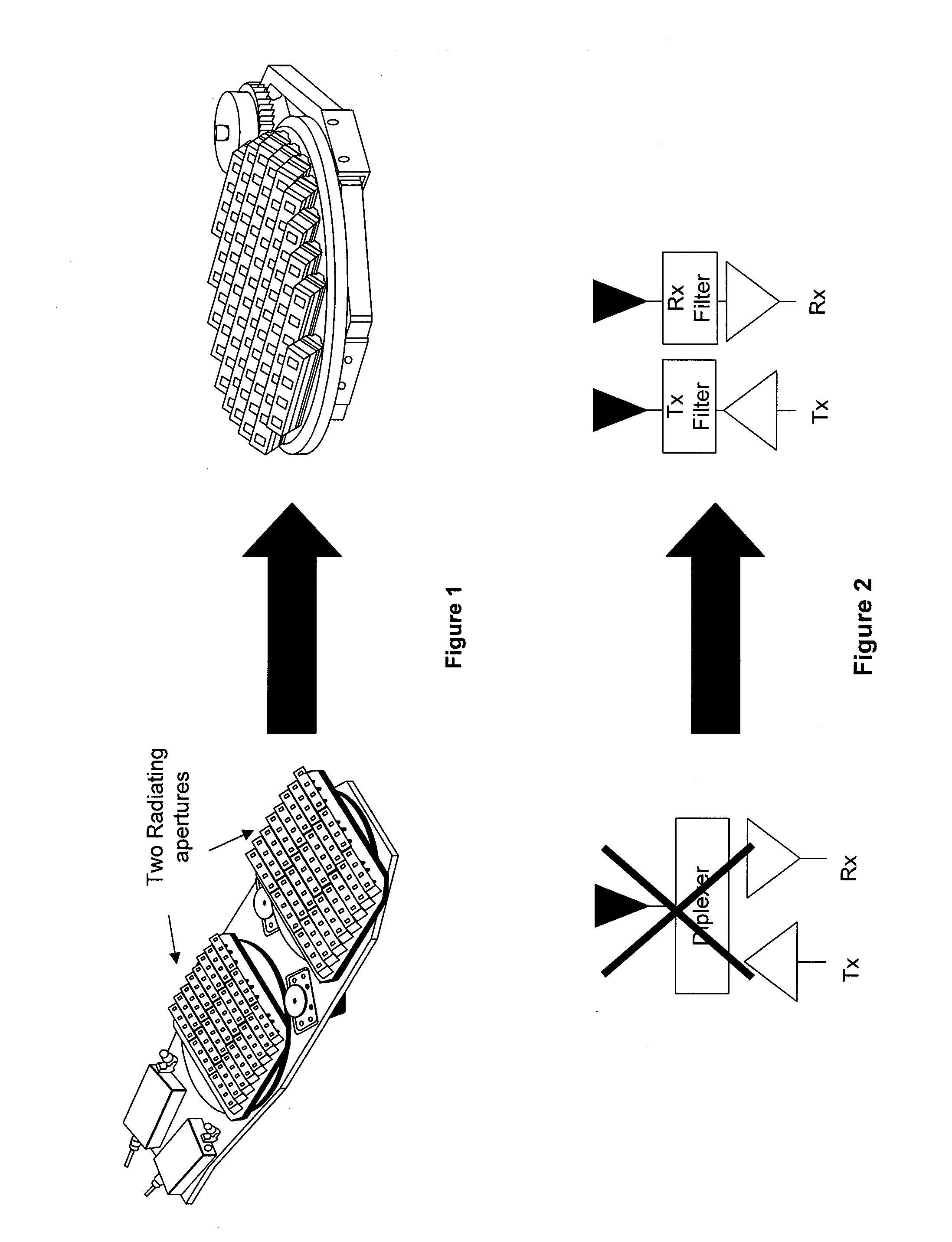
[0008]In an exemplary embodiment, an antenna architecture comprises a single aperture having both receive elements and transmit elements. Furthermore, in an exemplary embodiment, the array beam forming network and active circuitry are integrated into a low-profile structure, thus making it suitable for integration on vehicles for communications on the move.
[0010]In the exemplary embodiment, the shape of the receiving and transmitting patches is designed to integrate both receive and transmit elements in the antenna aperture while minimizing the coupling between the two types of elements. Moreover, different shapes of the apertures in the ground plane can have different effects on the performance of an antenna. For example, an H-shaped slot or a dual-C slot have the advantage to make the slot smaller compared to linear slots, thus reducing back radiation and increasing antenna efficiency.
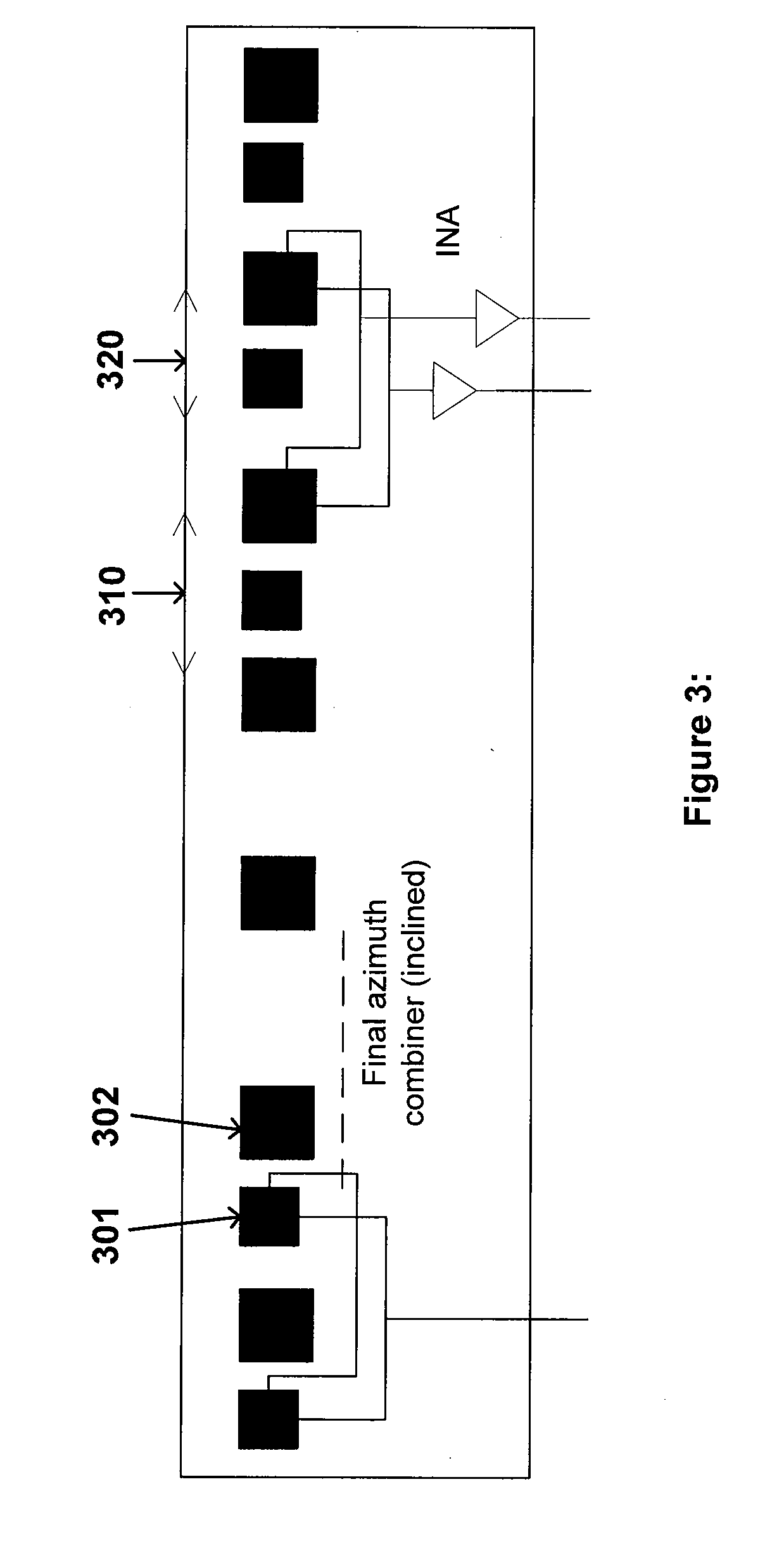
[0011]Moreover, in the case of an array with inclined elements, there is the need to interconnect a planar substrate, such as a printed circuit board (PCB) with an inclined substrate at an angle. In an exemplary embodiment, a planar PCB interconnects with an inclined PCB using a thick slot transition. A thick slot transition is a connecting hole through a core, where the planar PCB is located on one side of the core and the inclined PCB is located on the other side of the core. A benefit of implementing the cut-through interconnection of the two PCBs is the reduction of mechanical assembling, such as a reduction in the amount of soldering used to form a connection.

Problems solved by technology

The large bandwidths and the large spacing between bands make it difficult to design antenna arrays using the same aperture for both uplink and downlink functions.
However, using the same surface is difficult in array antennas where wideband elements tend to loose radiation efficiency in the required bands and where the integration of active components (e.g. for beam steering) includes a separation of transmit and receive signals at each element, generally resulting in an increase in costs and integration issues.
Additionally, integrating two types of elements, one for transmit and one for receive, in the same surface, may result in a high coupling between elements that affects quality of the radiation of the antenna.
Typically, the antenna design is very challenging because the spacing between radiating elements is very small and field couplings very high.
The high couplings between the two types of elements can cause problems on the generation of the beam forming and power isolation between the transmit and receive chain.
Overall, designing the receive function and the transmit function onto a single aperture may result in inefficiencies, increased complexity and cost, and high coupling between the radiating elements.

Method used


Image

  • Hybrid single aperture inclined antenna
  • Hybrid single aperture inclined antenna
  • Hybrid single aperture inclined antenna

Examples


Embodiment Construction

[0039]While exemplary embodiments are described herein in sufficient detail to enable those skilled in the art to practice the invention, it should be understood that other embodiments may be realized and that logical material, electrical, and mechanical changes may be made without departing from the spirit and scope of the invention. Thus, the following detailed description is presented for purposes of illustration only.

[0040]As illustrated in FIG. 1, an exemplary embodiment of an antenna array configuration integrates radiating elements, active components, and beam-forming networks of receive and transmit apertures in a single aperture. Furthermore, in an exemplary embodiment, the single aperture has equivalent size of one of prior art dual apertures, and still maintains the performance level of the dual aperture antenna.

[0041]In a typical antenna, a transmit radiating element and a receive radiating element are coupled to a diplexer to form a combined transmit and receive chain. ...


PUM


Abstract

In an exemplary embodiment, an antenna architecture comprises a single aperture having both receive elements and transmit elements, where the single aperture has the performance of a dual-aperture but in about half the size. Moreover, in the case of an array with inclined elements, there is the need to interconnect a planar substrate with an inclined substrate at an angle. An exemplary single aperture comprises a metal core having a thick pass-through slot from a first side to a second side; connecting the inclined substrate to the first side of the metal core, and connecting a second substrate to the second side of the metal core. Furthermore, an RF signal is communicated between the first substrate and the second substrate in a contactless manner through the thick pass-through slot.

Description

CROSS REFERENCE TO RELATED APPLICATIONS[0001]This application is a non-provisional of U.S. Provisional Application No. 61 / 221,504, entitled “HYBRID SINGLE APERTURE INCLINED ANTENNA,” which was filed on Jun. 29, 2009. This application is also a non-provisional of U.S. Provisional Application No. 61 / 250,775, entitled “HYBRID SINGLE APERTURE INCLINED ANTENNA,” which was filed on Oct. 12, 2009. This application is also a non-provisional of U.S. Provisional Application No. 61 / 323,285, entitled “DESIGN AND PROTOTYPING OF A MICROSTRIP TRANSMIT-RECEIVE ARRAY ANTENNA FOR MOBILE KU-BAND SATELLITE TERMINALS,” which was filed on Apr. 12, 2010. All of the contents of the previously identified applications are hereby incorporated by reference for any purpose in their entirety.FIELD OF THE INVENTION[0002]The present application relates to the structure of a radiating element, specifically to radio frequency (RF) connections between planar-to-planar and planar-to-inclined surfaces. Furthermore, the...

Claims


Application Information

Patent Timeline
Patent Type & Authority Applications(United States)
IPC IPC(8): H01Q1/38
CPCH01Q21/00H01P1/047H01Q21/065H01Q5/42
Inventor TIEZZI, FERDINANDOVACARRO, STEFANOLLORENS DEL RIO, DANIEL
Owner VIASAT INC
Learn More