
Circuit and method for beta variation compensation in single-transistor temperature sensor

Active Publication Date: 2010-12-30
TEXAS INSTR INC
View PDF8 Cites 18 Cited by
  • Summary
  • Abstract
  • Description
  • Claims
  • Application Information

AI Technical Summary

Benefits of technology

[0017]It is another object of the invention to provide a way of avoiding temperature measurement errors due to very low and / or widely varying values of the current gain β of a sensing transistor in an integrated circuit chip wherein fabrication process characteristics cause low and variable values of the current gain β of the sensing transistor.
[0019]It is another object of the invention to provide a way of automatically estimating the current gain β of a temperature sensing transistor in an integrated circuit chip wherein fabrication process characteristics cause low and variable values of the current gain β of the sensing transistor.

Problems solved by technology

While this technique is simple and robust, it has the disadvantages that it is quite variable due to temperature variation of the chip and also is variable with the excitation current I1, especially for a low value of β.
However, with line widths and spacings having values substantially less than 90 nanometers, that assumption becomes incorrect.
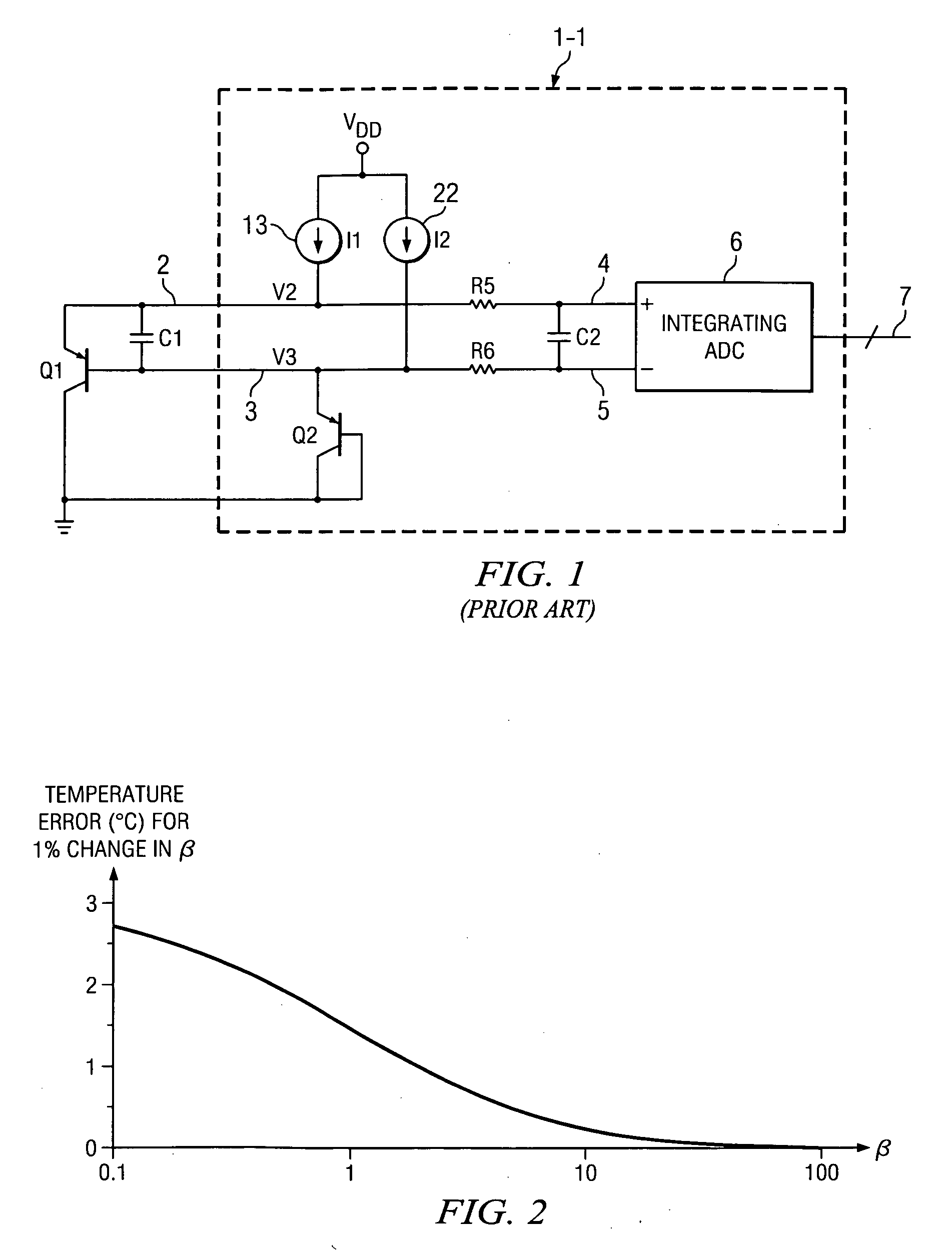
However, for present state-of-the-art manufacturing processes the chip-to-chip variation of the current gain β of the vertical PNP sensing transistor Q1 is great enough to cause large errors in the temperature measurements achieved by means of remote temperature sensor circuits such as the one shown in Prior Art FIG. 1.
However, in modern integrated circuit manufacturing processes, the β of a vertical PNP transistor typically is very low, and furthermore, β changes as a function of current.
That causes significant errors in the ability of the circuit shown in Prior Art FIG. 1 to accurately measure the junction temperature of sensing transistor Q1, because only the emitter current, rather than the collector current, is directly controlled.

Method used


Image

  • Circuit and method for beta variation compensation in single-transistor temperature sensor
  • Circuit and method for beta variation compensation in single-transistor temperature sensor
  • Circuit and method for beta variation compensation in single-transistor temperature sensor

Examples


Embodiment Construction

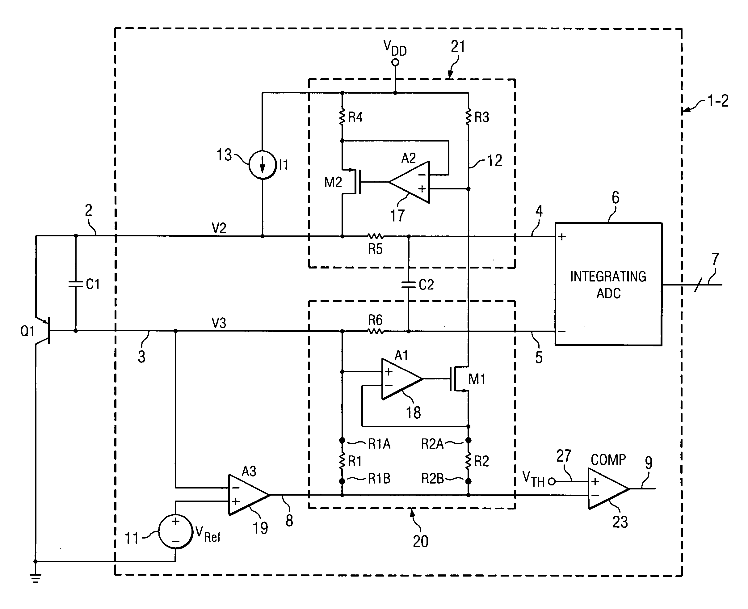
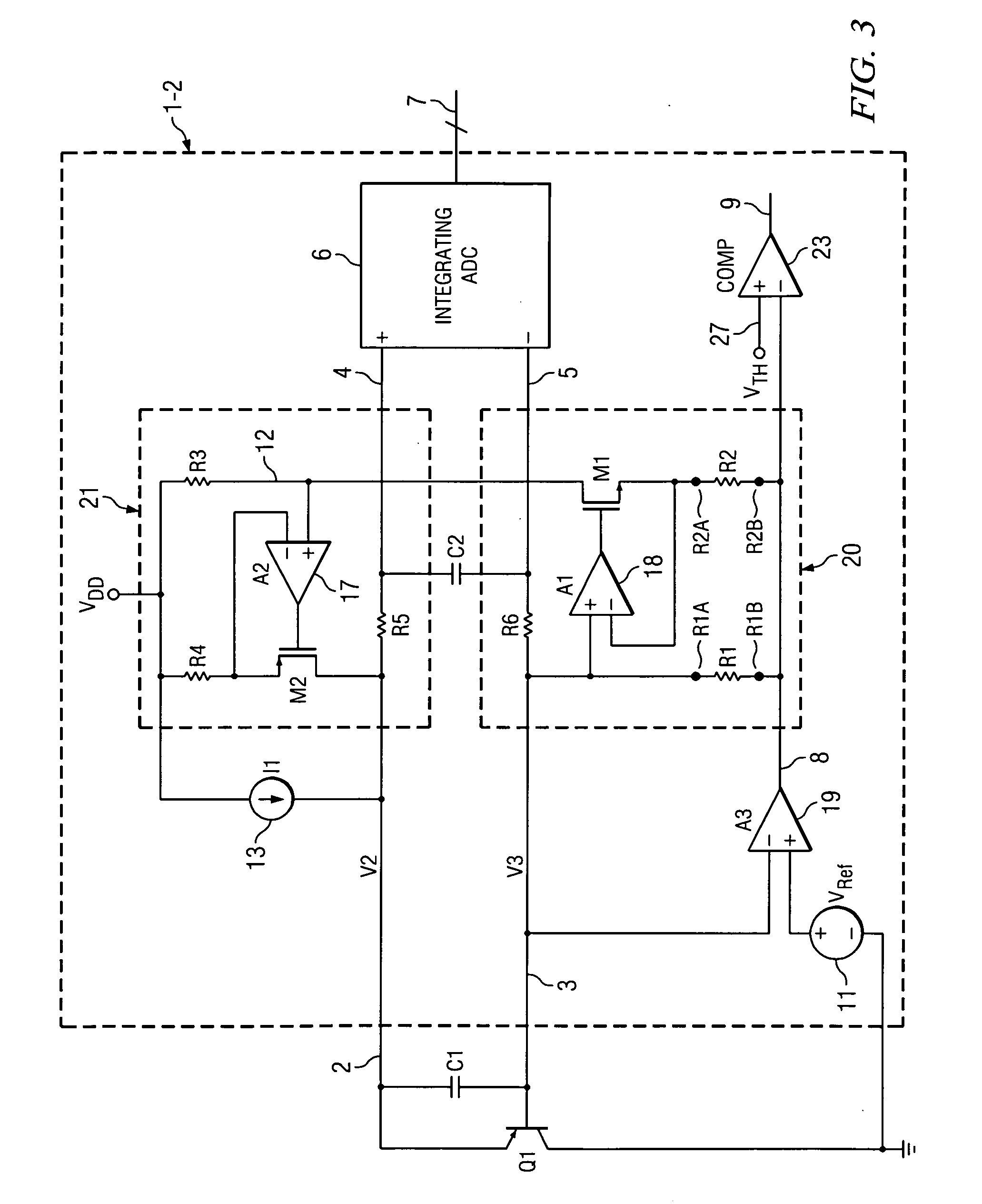
[0041]FIG. 3 shows a schematic diagram of a remote temperature sensor integrated circuit product 1-2 for sensing the junction temperature of a vertical PNP temperature-sensing transistor Q1 having its collector connected to ground. Sensing transistor Q1 may be located on the same integrated circuit chip as remote temperature sensor integrated circuit product 1-2 or on a different chip. The emitter of sensing transistor Q1 is coupled by conductor 2 and anti-aliasing filter R5,R6,C2 to a (+) input of an integrating ADC (analog-to-digital converter) circuit 6 which produces a digital output on bus 7. The base of sensing transistor Q1 is coupled by conductor 3 and anti-aliasing filter R5,R6,C2 to a (−) input of integrating ADC 6. A filter capacitor C1 is coupled between conductors 2 and 3. A current source 13, which may be programmable, is coupled between VDD and conductor 2 and generates a current I1. This much of remote temperature sensor 1-2 can be essentially the same as in Prior Ar...


PUM


Abstract

A circuit (1-2) for compensating for variations in the current gain β of a sensing transistor (Q1) having a collector coupled to a reference voltage (GND) includes a first current mirror (20) having an input coupled to a base of the sensing transistor. A second current mirror (21) has an input coupled to an output of the first current mirror. A current source (13) is coupled to provide emitter current for the sensing transistor. An output of the second current mirror circuit (21) feeds base current of the sensing transistor back to its emitter to cause the collector current of the sensing transistor to be precisely equal to the current (I1) provided by the current source.

Description

BACKGROUND OF THE INVENTION[0001]The present invention relates generally to circuits and methods of compensating for variations in the current gain beta (β) of a transistor, and more particularly to circuits and methods of compensating for variations in the β of a single transistor used to measure temperature in an integrated circuit.[0002]It is desirable to measure temperatures of silicon chips in various integrated circuit applications. One common method for achieving this is to measure a chip temperature using a single-temperature sensing transistor which has its base and emitter electrodes available for connection to temperature-measuring circuitry that may be on the same chip as the sensing transistor or on a different chip. The collector of the sensing transistor usually is connected to a reference voltage, such as ground or VDD.[0003]“Prior Art”FIG. 1 shows a schematic diagram of the Assignee's commercially available TMP 411 remote temperature sensor integrated circuit produc...

Claims


Application Information

Patent Timeline
IPC IPC(8): G01K7/00H03F3/14
CPCG01K7/01H03F2200/468H03F2200/447H03F1/302
Inventor DOORENBOS, JERRY L.
Owner TEXAS INSTR INC
Learn More