Liquid crystal display device

Inactive Publication Date: 2011-01-06
NEC CORP
View PDF4 Cites 61 Cited by
  • Summary
  • Abstract
  • Description
  • Claims
  • Application Information

AI Technical Summary

Benefits of technology

[0026]In the liquid crystal display device of the present invention, the heat exchange part includes an air stirring part which stirs the air in the housing part, a forced air cooling part covered with a duct in which the air stirring part is installed and which is constructed from a plate extending into the housing part, and a natural air cooling part constructed from a plate extending to the outside of the housing part. The forced air cooling part and the natural air cooling part are integrated with a rear face plate of the housing part.
[0027]Thereby, forced convection of the heat generated from the liquid crystal display device is caused by the heat stirring part, heat is moved to an upper portion of the device, and heat is induced toward the duct which covers the forced air cooling part. Hence, it is possible to efficiently transfer heat to the natural air cooling part from the forced air cooling part in the duct, reduce a temperature difference along with an absolute temperature reduction in the liquid crystal display device with sealing performance, and as temperature can be made to be uniform. Therefore, dust resistance and cooling performance can be simultaneously satisfied.
[0028]Therefore, it is possible to realize stabilization of the temperature of electronic circuit parts, such as a light source part, a power supply part, and a control part, the stabilization of luminance by lighting the fluorescent lamp at a constant luminance, and long life span of the liquid crystal panel by uniformizing temperature

Problems solved by technology

In this technique, however, dust including non-conductive and conductive substances which are scattered in ambient air enters a liquid crystal display device which is installed in public places, such as the partially outdoor areas, from the intake port provided in the liquid crystal display device.
Particularly, when dust including conductive substances has entered the inside of the liquid crystal display device, short circuiting may occur between electronic circuit parts mounted in the liquid crystal display device, may hinder reliability, and cause a problem in terms of the quality of the product.
For this reason, the conventional technique cannot be said to be satisfactory in terms of dust resistance and cooling performance in regard to a liquid crystal display device to be installed in public places, such as the partially outdoor areas.
However, in recent years, the power consumption of a back light serving as a light source part and an electric pow

Method used


Image

  • Liquid crystal display device
  • Liquid crystal display device
  • Liquid crystal display device

Examples


Example

FIRST EMBODIMENT

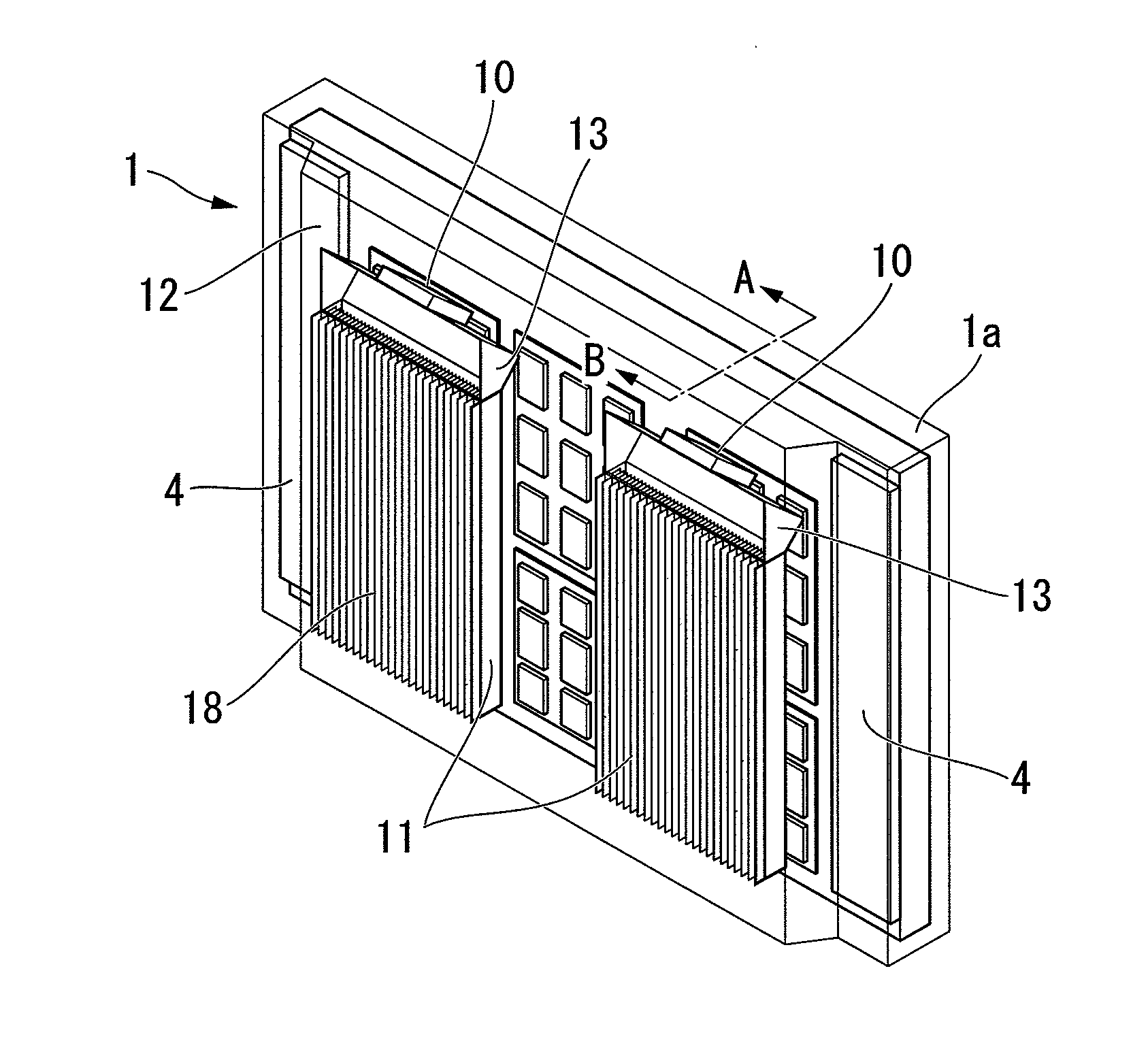
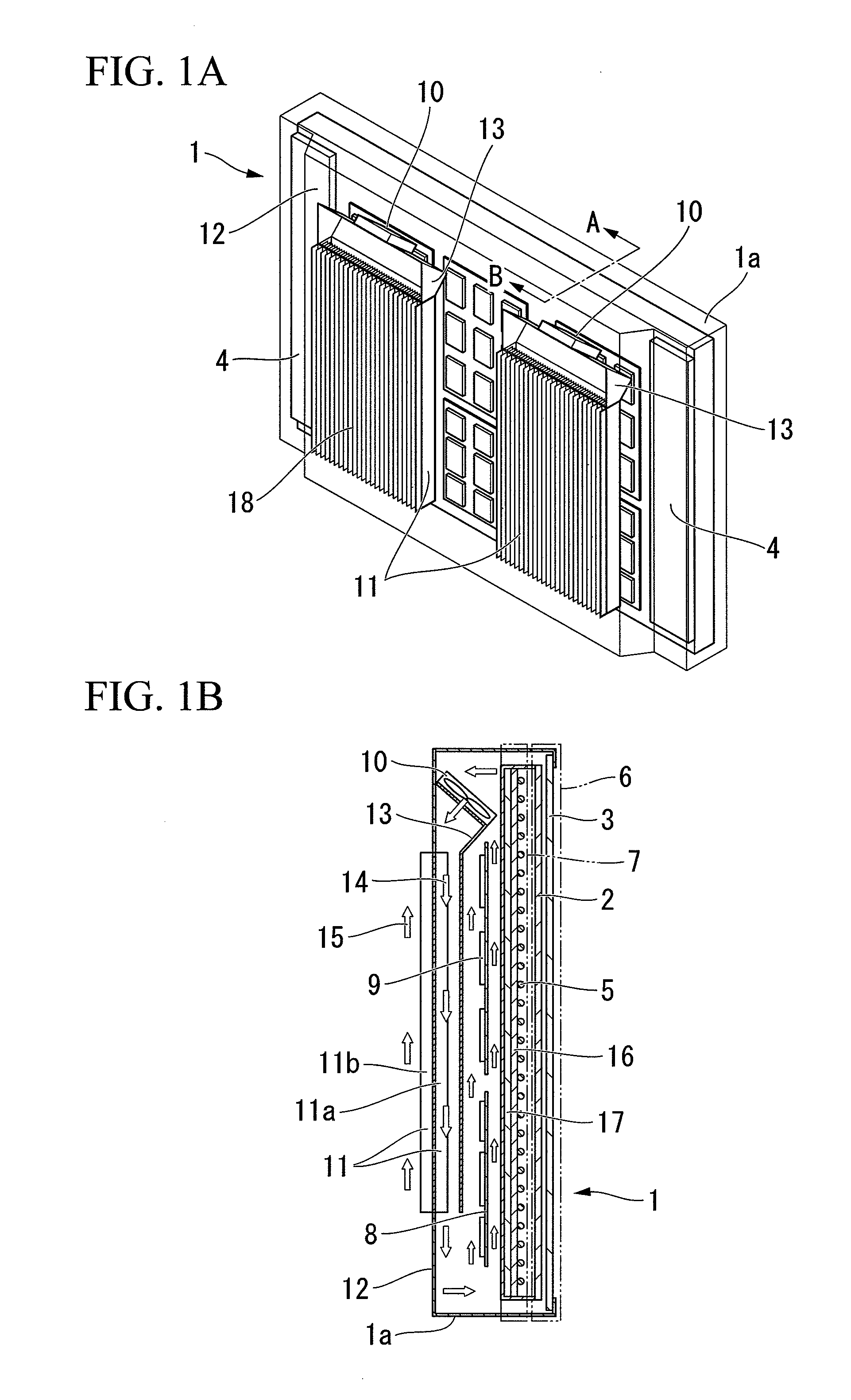
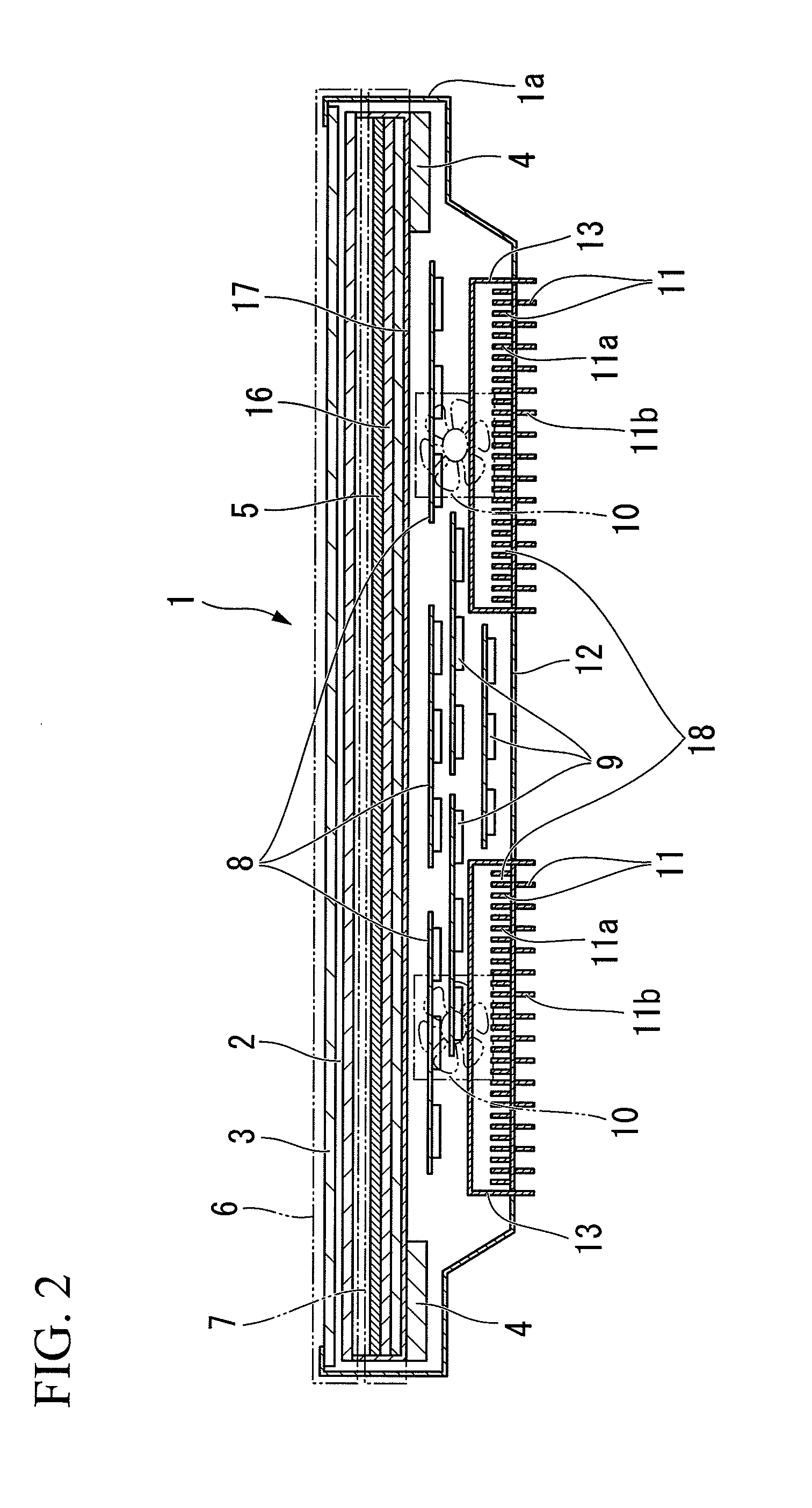
[0079]FIGS. 1A and 1B show the basic configuration of a liquid crystal display device 1 according to a first embodiment of the present invention. FIG. 1A is a perspective view of the liquid crystal display device 1. Additionally, FIG. 1B is a sectional view along a line A-B of FIG. 1A.

[0080]As shown in FIGS. 1A and 1B, the liquid crystal display device 1 includes a display part which has a fluorescent lamp 5 as a display light. Additionally, the liquid crystal display device 1 is mounted with a liquid crystal display part 6 in which the fluorescent lamp 5, an inverter circuit 4, a liquid crystal panel 2, or the like are housed, and an electric power supply part 8 to the liquid crystal display part 6, a control part 9 (light source, audio, personal computer function, or the like), or the like, which are at the rear face of the liquid crystal display part 6. Additionally, the liquid crystal display device 1 has, at a rear face plate 12 of a housing part 1a, an air sti...


PUM


Abstract

A liquid crystal display device includes a sealed housing part, a liquid crystal display part disposed at the front face of the housing part, a light source part housed in the housing part to generate the light to be displayed on the liquid crystal display part, an electric power supply part housed in the housing part to perform electric power supply, a control part housed in the housing part to perform control, and a heat exchange part disposed at the rear face of the housing part to cool the heat generated in the housing part. The heat exchange part includes an air stirring part for stirring the air in the housing part, a forced air cooling part covered with a duct in which the air stirring part is installed and constructed from a plate extending into the housing part, and a natural air cooling part constructed from a plate extending to the outside of the housing part. The forced air cooling part and the natural air cooling part are integrated with a rear face plate of the housing part.

Description

TECHNICAL FIELD[0001]The present invention relates to a large liquid crystal display device to be installed in public places, such as the partially outdoor areas of a train station platform, an airport lobby, or the like and particularly, to a sealed liquid crystal display device which prevents the entrance of dust which is scattered in ambient air.[0002]Priority is claimed Japanese Patent Application No. 2008-077962 filed on Mar. 25, 2008, the contents of which are incorporated herein by reference.BACKGROUND ART[0003]In a liquid crystal display device, in order to realize high reliability of the image quality uniformity, life span, or the like of a liquid crystal panel, a cooling technique is used which satisfies temperature standards to guarantee the operation of a light source part, a control part, and a power supply part.[0004]For this purpose, generally, a technique is used for providing an air intake port and an exhaust port, which introduce surrounding low-temperature air, in...

Claims


Application Information

Patent Timeline
IPC IPC(8): G02F1/1333
CPCG02F1/133385H05K7/20972G02F2201/36
Inventor MIKUBO, KAZUYUKIHASHIGUCHI, TAKEYASAKAMOTO, HITOSHI
Owner NEC CORP
Why Eureka
Try Eureka