
Photo-epilation device

a technology of photoepilation and device, which is applied in the field of photoepilation, can solve the problems of unsatisfactory results, high pain, blistering and/or hyperpigmentation,

Active Publication Date: 2011-01-06
KONINKLIJKE PHILIPS ELECTRONICS NV
View PDF10 Cites 17 Cited by
  • Summary
  • Abstract
  • Description
  • Claims
  • Application Information

AI Technical Summary

Benefits of technology

[0005]In another approach, aiming to reduce the overall size of the apparatus, high fluence is achieved by reducing the “footprint”, i.e. the skin area that can be treated. In a commercially available photo-epilation device, intended for the consumer market, the fluence is as high as 18 J / cm2 at a treatment window as low as 0.8 cm2. This obviously makes treatment of a substantial skin area such as an entire leg uncomfortably slow and tedious.
[0006]It is an object of the present invention to provide a photo-epilation device that can be comfortably used by consumers at home, with little or no risk of side effects, and with little or no risk of unacceptably high levels of pain.
[0007]It is a further object of the present invention to provide a photo-epilation device that can be used by consumers of all skin types, without the need of well-trained professionals for operating the device.
[0008]It is another object of the present invention to provide a photo-epilation device that is relatively small. Particularly, the present invention has for its object to provide a hand-held and easily transportable photo-epilation device.
[0009]In accordance with an important aspect of the present invention, a low fluence setting which is still effective is chosen, dependent on the skin type. This keeps heat generation low, and thus allows effective cooling to be achieved by a simple fan blowing ambient air at a low flow rate, and ultimately allows a smaller size of the apparatus.

Problems solved by technology

However, a problem is that there are different skin types.
If the fluence is too low for a certain skin type, the obtained result may be unsatisfactory.
If the fluence is too high for a certain skin type, the melanin in the epidermis will absorb too much light and, consequently, undesirable effects such as blistering and / or hyperpigmentation, and / or high levels of pain are likely to occur.
Such professional systems are bulky, heavy, and expensive.
Consequently, they are not suitable for the consumer market.
This obviously makes treatment of a substantial skin area such as an entire leg uncomfortably slow and tedious.

Method used


Image

  • Photo-epilation device
  • Photo-epilation device

Examples


Embodiment Construction

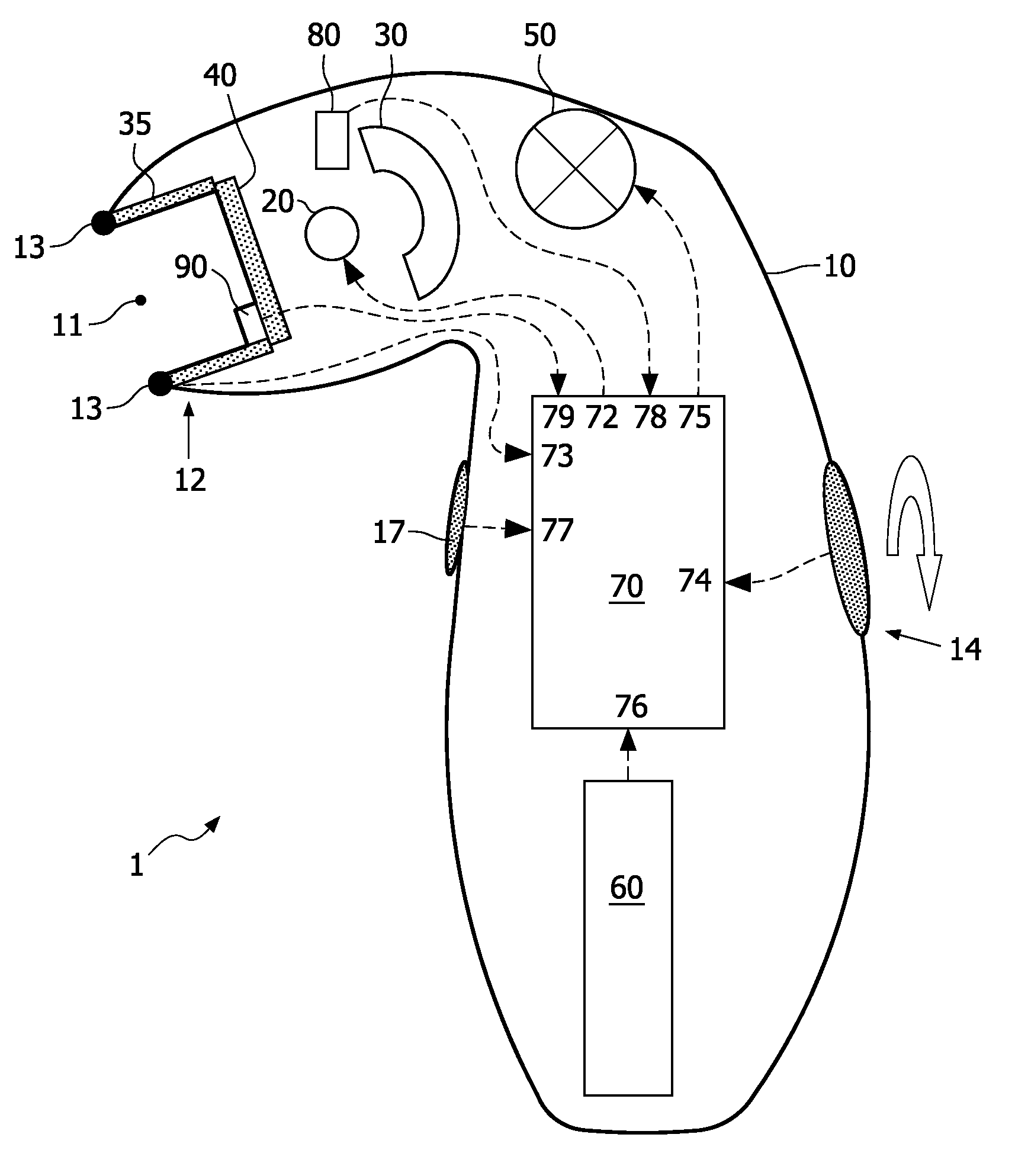
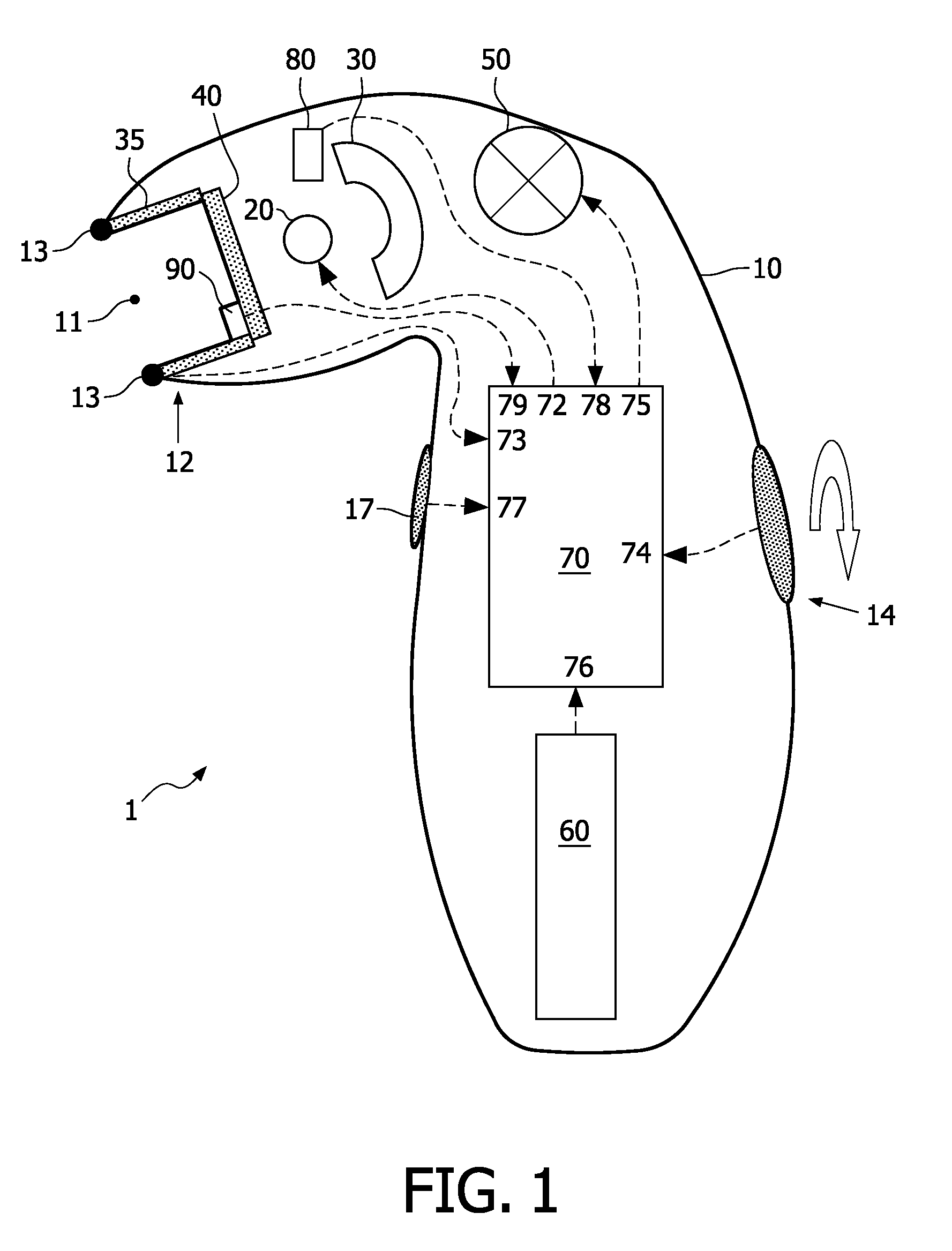
[0014]FIG. 1 schematically illustrates a hand-held photo-epilation device 1 according to the present invention. The device comprises a housing 10, the size of which is comparable to the size of a shaving device. The housing 10 accommodates at least one intense broadband light source 20. The light source 20, hereinafter also referred to as “lamp”, is suitably implemented as a Xenon flash lamp, but other types of lamps may also be used, provided they produce a light spectrum which is suitable to achieve photo-epilation. Since Xenon flash lamps are known per se, a further explanation is not necessary.

[0015]The housing 10 is substantially closed, yet has one window opening 11 (although the housing may also have a plurality of window openings) for allowing light generated by the lamp 20 to exit the housing. The edges of the window opening 11 will be referred to as the mouth 12 of the device 1. A preferred shape of the window opening is substantially rectangular, and a preferred size is a...


PUM


Abstract

A photo-epilation device (1) comprises: a hand-held housing (10) with at least one window opening (11); a lamp (20) accommodated in the housing for generating light having a spectral range from approximately 575 nm to approximately 1700 nm; and a control device (70) for driving the lamp (20). The lamp is switched on in brief pulses having a pulse duration in the range from 1.1 ms to 1.9 ms, preferably about 1.8 ms, and a pulse repetition frequency in the range from 0.1 Hz to 0.5 Hz. The fluence on skin level is in the range from 2 to 7 J / cm2, dependent on the skin type, particularly from: 5 to 7 J / cm2 for skin types I, II, III; 4 to 6 J / cm2 for skin type IV; 3 to 5 J / cm2 for skin type V; and 2 to 3 J / cm2 for skin type VI.

Description

FIELD OF THE INVENTION[0001]The present invention relates in general to photo-epilation, i.e. (temporary or permanent) hair removal by light.BACKGROUND OF THE INVENTION[0002]Photo-epilation is known per se; by way of example, reference is made to U.S. Pat. No. 5,735,844. Light originating from a suitable light source (laser; flash lamp) is absorbed by melanin in a hair and / or follicle. The absorbed light is converted into heat. This heat damages or even destroys the follicle. The hair is shed, and new growth is delayed or even fully prevented.[0003]The light is typically applied in pulses. There are several parameters that play a role in epilation efficiency: pulse duration, pulse repetition frequency, wavelength or spectral range of the light, and fluence (or energy density, expressed in J / cm2). When permanent hair removal and thus follicle destruction is intended, literature reports fluences as high as 60 J / cm2 applied in pulses in the range from a few ms to a few hundred ms. U.S....

Claims


Application Information

Patent Timeline
Patent Type & Authority Applications(United States)
IPC IPC(8): A61B18/18
CPCA61B18/203A61B2017/00154A61B2017/00181A61B2018/00452A61B2018/00476A61N2005/0654A61B2018/202A61B2019/465A61N5/0617A61N2005/0644A61B2018/1807A61B2090/065A45D26/00A61B17/00A61N5/06
Inventor NUIJS, ANTONIUS MAARTENEVERS-DERKX, LENIE JOHANNA THEODORA
Owner KONINKLIJKE PHILIPS ELECTRONICS NV
Learn More