Brake for a work machine, a wheel hub unit and a work machine

Inactive Publication Date: 2011-01-13
VOLVO CONSTR EQUIP
View PDF21 Cites 1 Cited by
  • Summary
  • Abstract
  • Description
  • Claims
  • Application Information

AI Technical Summary

Benefits of technology

[0007]It is desirable to provide a hydraulically operated brake which is adapted to at least reduce the jerks resulting from brake actuation and which creates conditions for a more cost-efficient brake system. Further, the brake should provide good controllability.
[0009]The brake rotor design reduces the sensitivity of the brake at the initiation in that the damping layer is adapted to absorb energy. In other words, the damping layer functions as a cushioning means.
[0010]A secondary effect is that the noise from the actuation of the brake is eliminated.

Problems solved by technology

This excess pressure surge gives rise to a brake shock (a powerful retardation of the machine), which the driver experiences as a jerk.
Such a jerk results in that the driver is exposed to vibrations.
The excess pressure surge also results in that the components of the brake being exposed to heavy stresses, which among other things generates noise.
The noise is experienced by the driver and persons near the machine as an irritation.
The brake rotor design reduces the sensitivity of the brake at the initiation in that the damping layer is adapted to absorb energy.

Method used


Image

  • Brake for a work machine, a wheel hub unit and a work machine
  • Brake for a work machine, a wheel hub unit and a work machine
  • Brake for a work machine, a wheel hub unit and a work machine

Examples


Embodiment Construction

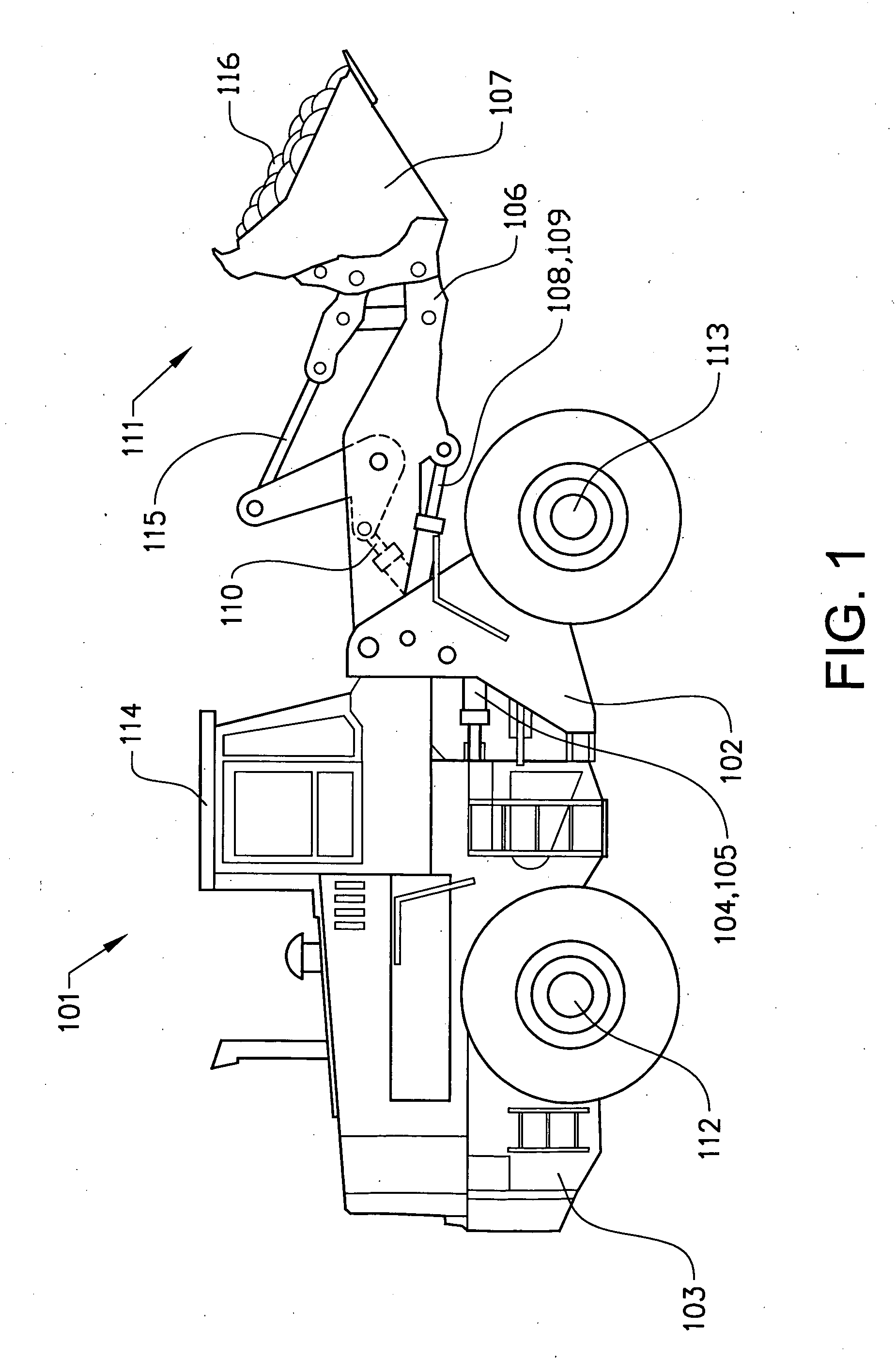
[0020]FIG. 1 shows a frame-steered work machine constituting a wheel loader 101. The body of the wheel loader 101 comprises a front body section 102 and a rear body section 103, which sections each has an axle 112,113 for driving a pair of wheels. The rear body section 103 comprises a cab 114. The body sections 102,103 are connected to each other in such a way that they can pivot in relation to each other around a vertical axis by means of two first actuators in the form of hydraulic cylinders 104,105 arranged between the two sections. The hydraulic cylinders 104,105 are thus arranged one on each side of a horizontal centerline of the vehicle in a vehicle traveling direction in order to turn the wheel loader 101.

[0021]The wheel loader 101 comprises an equipment 111 for handling an external load, such as objects or material. The equipment 111 comprises a load-arm unit 106 and an implement 107 in the form of a bucket fitted on the load-arm unit. A first end of the load-arm unit 106 is...


PUM


Abstract

A brake for a work machine includes a brake rotor, a hydraulically operated device for actuating the brake by clamping the brake rotor, and an arrangement for damping jerks resulting from a sudden brake actuation. The brake rotor includes a pair of brake force transmitting discs and the damping arrangement is formed by a damping layer positioned between the discs and secured to each of the discs.

Description

BACKGROUND AND SUMMARY[0001]The present invention relates to a brake for a work machine, wherein the brake comprises a brake rotor, a hydraulically operated device for actuating the brake by clamping the brake rotor, and means for damping jerks resulting from a sudden brake actuation. The invention further relates to a wheel hub unit comprising the brake and a work machine comprising the wheel hub unit.[0002]The invention can be applied in vehicles or work machines which are intended to be driven on a relatively flat surface, such as a road, and / or on uneven ground off road. The invention is—especially applicable for a relatively slow moving work machine, such as a wheel loader. By the term “relatively slow moving” is meant a vehicle / work machine with a maximum speed of about 50 km / h.[0003]A wheel loader must be equipped with brakes that are suited for the varying characteristics of the machine. In one extreme case, a fully loaded machine must be powerfully retarded and in another e...

Claims


Application Information

Patent Timeline
IPC IPC(8): F16D55/22F16D65/12F16D55/225B60B27/04B60B27/00
CPCF16D65/0006F16D65/12F16D2121/02F16D2069/004F16D2065/132
Inventor STRANDBERG, JONNYDAHLEN, TORD
Owner VOLVO CONSTR EQUIP
Why Eureka
Try Eureka