Fuel pressure measuring device, fuel pressure measuring system, and fuel injection device

a technology of fuel pressure measurement and measuring system, which is applied in the direction of liquid transfer devices, machines/engines, electric control, etc., can solve the problems of reducing the accuracy of determining such pressure changes, and achieve the effect of ensuring the accuracy of measuring pressure, facilitating machining or forming of diaphragms, and facilitating the control of the thickness of diaphragms

Active Publication Date: 2011-01-13
DENSO CORP
View PDF15 Cites 23 Cited by
  • Summary
  • Abstract
  • Description
  • Claims
  • Application Information

AI Technical Summary

Benefits of technology

[0025]The invention, as recited in claim 12, is characterized in that the separate member includes an inner orifice into which the high-pressure fluid is delivered, a pressure control chamber space which communicates with the inner orifice and constitutes a portion of the pressure control chamber, and an outer orifice which communicates with the pressure control chamber space and discharges the high-pressure fluid to a low-pressure path, and in that the branch path communicates with the pressure control chamber space in the separate member, and the diaphragm connects with the branch path and is formed in the separate member. The branch path communicating with the pressure control chamber and the diaphragm are disposed in the separate member formed to be separate from the injector body, thus facilitating the ease of machining or forming the diaphragm. This also facilitates controlling the thickness of the diaphragm as compared with the effects of the invention of claim 10, thus ensuring the accuracy in measuring the pressure.
[0026]The invention, as recited in claim 13, is characterized in that the branch path connects with a portion of the pressure control chamber space which is different from that to which the inner orifice and the outer orifice connect. The flow of the high-pressure fluid in the inner orifice and the outer orifice is fast, thus resulting in a time lag until a change in pressure is in the steady state. However, the present invention uses the above structure, thus enabling a change in the pressure to be measured in a range in which the flow in the pressure control chamber is in the steady state.
[0027]The invention, as recited in claim 14, is characterized in that the separate member includes a first member equipped with the inner orifice, the pressure control chamber space, and the outer orifice, and a second member which is stacked directly or indirectly on the first member within the injector body, has the connection path and the branch path, and in which the diaphragm connects with a portion of the branch path which is different from that to which the connection path connects.
[0028]The thin-walled portion is in the second member formed to be separate from the injector body, thus facilitating the ease of machining or forming the diaphragm. This also facilitates controlling the thickness of the diaphragm, thus ensuring the accuracy in measuring the pressure. Further, the second member including the diaphragm is stacked on the first member defining the portion of the pressure control chamber, thus avoiding an increase in diameter of the injector body.
[0029]The invention, as recited in claim 15, is characterized in that the second member is made of a plate member having a given thickness, the displacement measuring means includes a strain measuring device installed on a surface of the diaphragm of the second member which is opposite a surface thereof to which the high-pressure fluid is introduced, and the diaphragm is located at a depth of at least a thickness of the strain measuring device below a surface of the second member.
[0030]The diaphragm is located at the depth of at least the thickness of the strain measuring device below the surface of the second member, thus avoiding the stress on the strain measuring device when the second member is disposed in the injector body. This facilitate the installation of the pressure sensing portion in the second member.

Problems solved by technology

When such a change in pressure of the fuel is measured by a fuel pressure sensor (i.e., a rail pressure sensor) installed directly in a common rail (i.e., an accumulator), it will be absorbed within the common rail, thus resulting in a decrease in accuracy in determining such a pressure change.

Method used


Image

  • Fuel pressure measuring device, fuel pressure measuring system, and fuel injection device
  • Fuel pressure measuring device, fuel pressure measuring system, and fuel injection device
  • Fuel pressure measuring device, fuel pressure measuring system, and fuel injection device

Examples


first embodiment

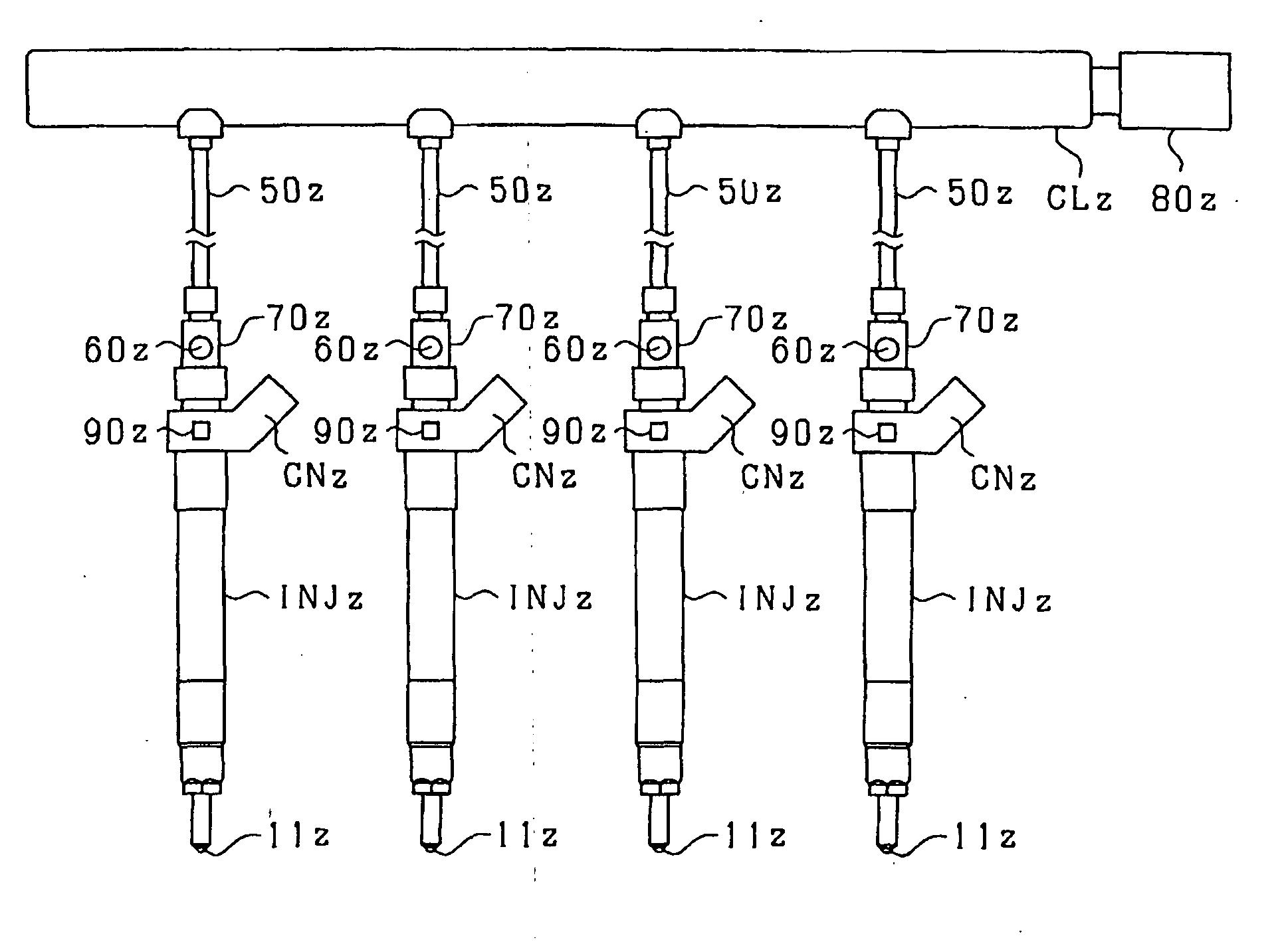
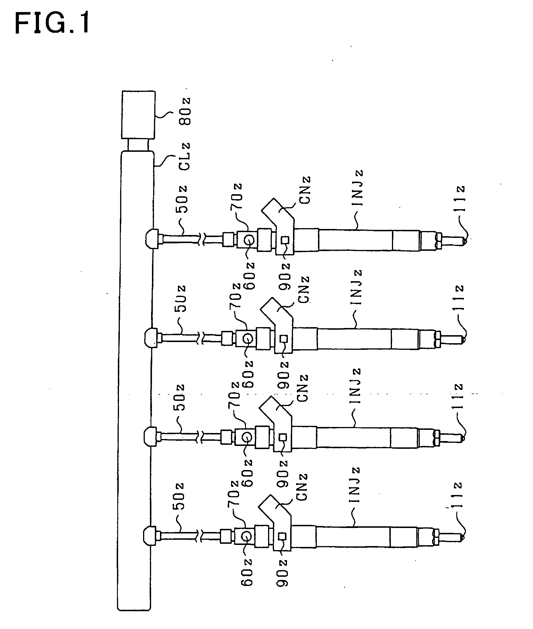
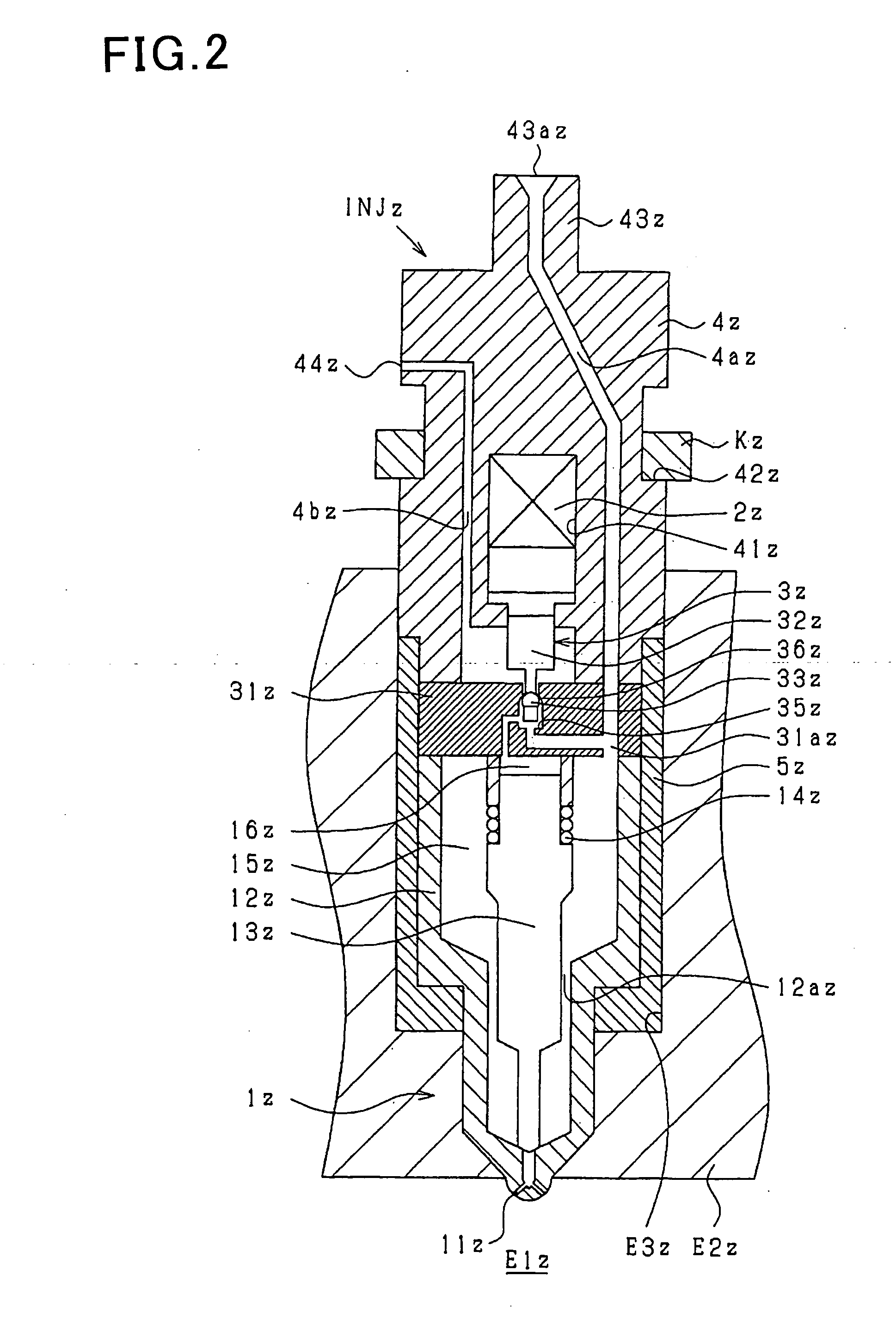
[0207]The first embodiment of the invention will be described using FIGS. 1 to 3. FIG. 1 is a view which shows injectors INJz (i.e., a fuel injection valve) of this embodiment which are joined to a common rail CLz (i.e., an accumulator). FIG. 2 is a sectional view which shows one of the injectors INJz. FIG. 3 is a view which shows a mount structure of a strain gauge 60z (i.e., a strain sensor).

[0208]The basic structure and operation of the injector will be described based on FIGS. 1 and 2. The injector INJz works to spray high-pressure fuel, as accumulated in the common rail CLz, into a combustion chamber E1z formed in a cylinder of an internal combustion engine. The injector INJz is installed in a cylinder head E2z of the engine.

[0209]This embodiment is made for a diesel engine (i.e., an internal combustion engine) for four-wheel automobiles which is of a type in which high-pressure fuel (e.g., light fuel) is to be injected directly into the combustion chamber E1z at an atmospheric...

second embodiment

[0232]In the first embodiment, the connector 70z which connects between the injector INJz and the high-pressure pipe 50z has the thin-walled portion 70bz. In this embodiment, as illustrated in FIG. 4, the injector body 4z (path member) has the thin-walled portion 43bz.

[0233]Specifically, a side surface portion of the high-pressure fuel path 4az of the injector body 4z adjacent the high-pressure port 43z has formed therein the thin-walled portion 43bz which has a locally thin wall thickness. The strain gauge 60z is affixed to the outer peripheral surface of the thin-walled portion 43bz (i.e., the surface far from the high-pressure fuel path 4az). In other words, the injector body 4z has formed in the outer peripheral surface thereof a recess 43cz to define the thin-walled portion 43bz. The strain gauge 60z and circuit components 61z are disposed in the recess 43cz.

[0234]The electric connector CNz has an engaging portion CN1 extending along the outer peripheral surface of the inject...

third embodiment

[0237]The injector INJz is, as described above, mounted in the insertion hole E3z of the cylinder head E2z. The second embodiment has the thin-walled portion 43bz formed in the injector body 4z outside the insertion hole E3z. In this embodiment, as illustrated in FIG. 5, the thin-walled portion 4cz is formed in a portion of the injector body 4z which is located inside the insertion hole E32.

[0238]Specifically, the thin-walled portion 4cz is formed at the most downstream location of the high-pressure fuel path 4az in the injector body 4z. The strain gauge 60z is affixed to the outer peripheral surface of the thin-walled portion 4cz (i.e., the surface far from the high-pressure fuel path 4az). In other words, the injector body 4z has formed in the outer peripheral surface thereof a recess 4dz to define the thin-walled portion 4cz. The strain gauge 60z and circuit components 61z are disposed in the recess 4dz.

[0239]The lead wires (not shown) joined to the strain gauge 60z may be array...


PUM


Abstract

It is used with a fuel injection system for an internal combustion engine which supplies fuel to an injector (fuel injection valve) from a common rail (accumulator) through a high-pressure pipe to spray the fuel from a spray hole formed in the injector. A thin-walled portion 70bz is formed in a path member (e.g., an injector body 4z, the high-pressure pipe, or a connector 70z connecting the injector and the high-pressure pipe) and defined by a locally thin wall of the path member. A strain gauge 60z (strain sensor) is affixed to the thin-walled portion 70bz to measure strain of the thin-walled portion 70bz arising from the pressure of fuel in a high-pressure fuel path 70az.

Description

TECHNICAL FIELD[0001]The present invention relates generally to a fuel pressure measuring device, a fuel pressure measuring system, and a fuel injection device to measure the pressure of fuel in a fuel injection system for an internal combustion engine into which the fuel, as supplied from an accumulator, is sprayed by a fuel injection valve.BACKGROUND ART[0002]In order to ensure the accuracy in controlling output torque of internal combustion engines and the quantity of exhaust emissions therefrom, it is essential to control a fuel injection mode such as the quantity of fuel to be sprayed from a fuel injector or the injection timing at which the fuel injector starts to spray the fuel. For controlling such a fuel injection mode, there have been proposed techniques for sensing a change in pressure of the fuel resulting from spraying thereof from the fuel injector.[0003]For instance, the time when the pressure of the fuel begins to drop due to the spraying thereof from the fuel inject...

Claims


Application Information

Patent Timeline
Patent Type & Authority Applications(United States)
IPC IPC(8): B67D7/08
CPCF02M47/027F02M2547/001F02M57/005F02M2200/24F02M51/005F02D41/3845
Inventor KONDO, JUNTAGUCHI, TOORUTANADA, HIROKIYAMANAKA, AKITOSHI
Owner DENSO CORP
Why Eureka
Try Eureka