
Method and apparatus for ebeam treatment of webs and products made therefrom

Active Publication Date: 2011-01-13
HITACHI ZOSEN CORP
View PDF29 Cites 13 Cited by
  • Summary
  • Abstract
  • Description
  • Claims
  • Application Information

AI Technical Summary

Benefits of technology

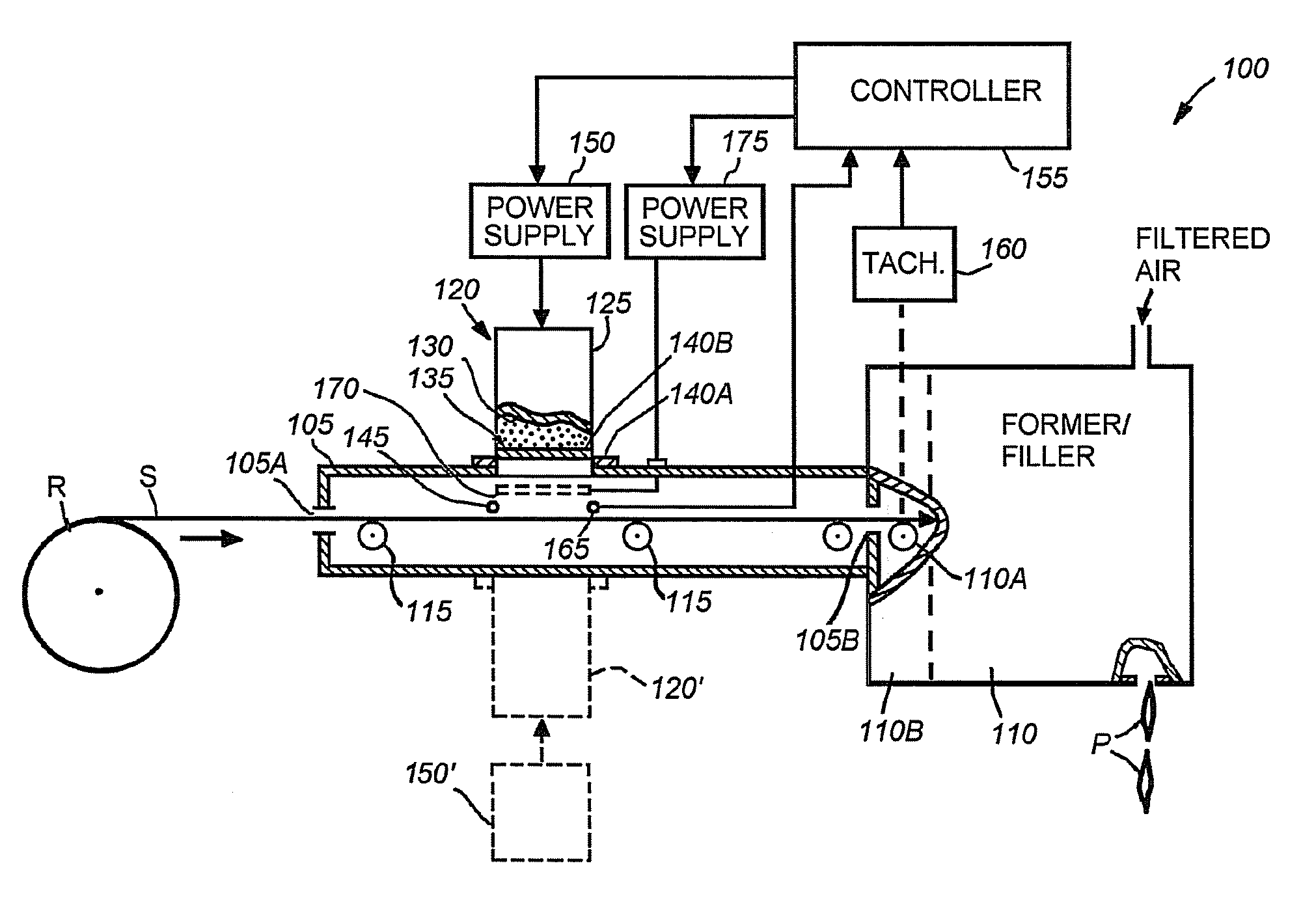
[0021]The disadvantages of the prior art are overcome by providing a method and apparatus for sterilization of webs and products made therefrom using electronic beams (ebeams). Illustratively, when packaging material is advanced in a non-continuous manner through the irradiation zone of an electron beam from an ebeam emitter, the ebeam dose delivered to the material is kept within a desired range that will effectively sterilize the material without adversely effecting same. This is accomplished by controlling, as a function of the advance of the material along the process line, the beam energy output from the emitter and / or the “transmission factor” of an electron beam modulator located in the path of the beam so as to maintain the current density of the ebeam at the packaging material in the emitter's irradiation zone with a desired range. The beam energy output from the emitter can be varied while maintaining near-constant thermal load on the window by simultaneously varying current and voltage. The modulator may comprise an electron mask or scatterer or one more movable shutters that that can partially or completely block the beam energy emanating from the emitter's exit window in order to control the electron beam dosage delivered to the substrate. During such treatment of the packaging material, the beam energy output from the emitter may also be controlled as a function of the packaging material advance to maintain the thermal load on the emitter's exit window within a desired range that maximizes the useful life of that window.
[0022]Thus, it is contemplated within this invention that the ebeam dose applied by the emitter to the packaging material may be adjusted solely by controlling the beam modulator as a function of the packaging material advance, in which case the electron beam may run at a constant voltage and current. By the same token, the beam modulator may be controlled so as to not interfere with the ebeam at all, leaving the dose being applied to the packaging material controlled solely by regulating the emitter's ebeam current and voltage. In any event, the emitter is controlled to manage the heat load on the emitter's exit window to keep that load within a safe range when delivering the desired ebeam dosage to the packaging material.

Problems solved by technology

Sterilization of the packaging material typically leads to a longer shelf life of the product that is packaged therein.
In order to maintain a dose delivery to the packaging material that falls within the required range for a particular application it is be desirable to modulate the effective dose delivery as a function of the speed S. However, modifying the ebeam dose applied to the packaging material necessitated by the non-continuous advance thereof may have an adverse effect on the ebeam emitter.
During normal operation of the emitter, the exit window will absorb some amount of the electron energy which results in heating of the foil.
If that heating is excessive, the foil may fail.
Since the foil constitutes part of the wall of the vacuum chamber, such a failure will cause the vacuum chamber to lose its vacuum, thereby disabling the emitter.
The thermal stresses on the exit window are particularly great if the emitter output power is cycled rapidly, thereby creating more dramatic thermal cycling of the foil than if the emitter were operated at a constant power output.
A known disadvantage of the prior art arrives when the emitter is being used to treat packaging material which is advanced in a non-continuous manner.
A known disadvantage of the prior art is that some of that SIP sterilant may damage the electron beam system if substantial amounts of vaporized sterilant come into direct contact with the electron beam window.

Method used


Image

  • Method and apparatus for ebeam treatment of webs and products made therefrom
  • Method and apparatus for ebeam treatment of webs and products made therefrom
  • Method and apparatus for ebeam treatment of webs and products made therefrom

Examples


Embodiment Construction

[0033]A. Modulation of Window Control

[0034]FIG. 1 illustrates an exemplary aseptic packaging apparatus environment 100 in which a packaging substrate S drawn from a roll R is conducted through a slit 105A at the entrance end of an elongated housing 105 whose exit end is connected to an exemplary processing machine 110. Substrate S is guided along housing 105 by a series of guide rollers 115 to an exit slit 105B that connects housing 105 to the interior of machine 110. Thereafter, the guidance of the substrate is taken over by a guide roller 110A in that machine. Substrate S is illustratively comprised of plastic film. It should be noted that in alternative embodiments, differing substrates may be utilized. As such, the description of substrate S being comprised of plastic film should be taken as exemplary only.

[0035]The illustrated machine 110 is illustratively a forming and filling machine which may be of any known type. Machine 110 accepts the substrate S and illustratively forms ...


PUM

PropertyMeasurementUnit
Densityaaaaaaaaaa
Speedaaaaaaaaaa
Electric potential / voltageaaaaaaaaaa

Abstract

A method and apparatus for sterilization of webs and products made therefrom using electron beams (ebeams) is provided. A controller is configured to modulate an ebeam to ensure that a non-continuously moving web is sterilized within a desired range of exposure. During sterilization in place operations, manifolds are configured to operate to ensure that sterilants do not enter an irradiation zone to prevent damage to ebeam emitters.

Description

CROSS REFERENCE TO RELATED APPLICATIONS[0001]The present application claims priority to U.S. Provisional Application No. 61 / 223,446, filed on Jul. 7, 2009 by Bufano et al., for METHOD AND APPARATUS FOR EBEAM TREATMENT OF WEBS AND PRODUCTS MADE THEREFROM, the contents of which are hereby incorporated by reference.[0002]The present application also claims priority to U.S. Provisional Application No. 61 / 288,569, filed on Dec. 21, 2009 by Thomson et al., for SHIELDING FOR ELECTRON BEAN STERILIZATION, the contents of which are hereby incorporated by reference.FIELD OF THE INVENTION[0003]The present invention relates generally to sterilization of packaging materials, and more specifically to sterilization of web based packaging materials using electron beams.BACKGROUND OF THE INVENTION[0004]Electron beam (ebeam) emitting apparatus have been used over the years to treat moving webs for various purposes, such as to sterilize a web of packaging material, polymerize web material, cure a coati...

Claims


Application Information

Patent Timeline
IPC IPC(8): B65B55/08B65B1/02
CPCA61L2/087A61L2202/14A61L2/24
Inventor FLETCHER, P. MICHAELSOMERSTEIN, ARTHURHOFFMASTER, JAMESBUFANO, MICHAEL LAWRENCEINTO, STEPHEN WHITTACKER
Owner HITACHI ZOSEN CORP
Learn More