Correction of spot area in measuring brightness of sample in biosensing device

a biosensing device and spot correction technology, applied in the field of biosensing devices, can solve the problems of only being operated by trained personnel, large and expensive instruments, and inability to transfer cell analysis to micro-fabricated systems, etc., and achieves the effect of not being suitable for roadside use or other instant tests

Inactive Publication Date: 2011-01-13
KONINKLIJKE PHILIPS ELECTRONICS NV
View PDF18 Cites 25 Cited by
  • Summary
  • Abstract
  • Description
  • Claims
  • Application Information

AI Technical Summary

Benefits of technology

[0026]How the present invention may be put into effect will now be de...

Problems solved by technology

However, they are large and expensive instruments and can only be operated by trained personnel.
Recently, considerable effort has been put into transferring cell analysis to micro fabric...

Method used


Image

  • Correction of spot area in measuring brightness of sample in biosensing device
  • Correction of spot area in measuring brightness of sample in biosensing device
  • Correction of spot area in measuring brightness of sample in biosensing device

Examples


first embodiment

FIG. 1, a Biosensing Device

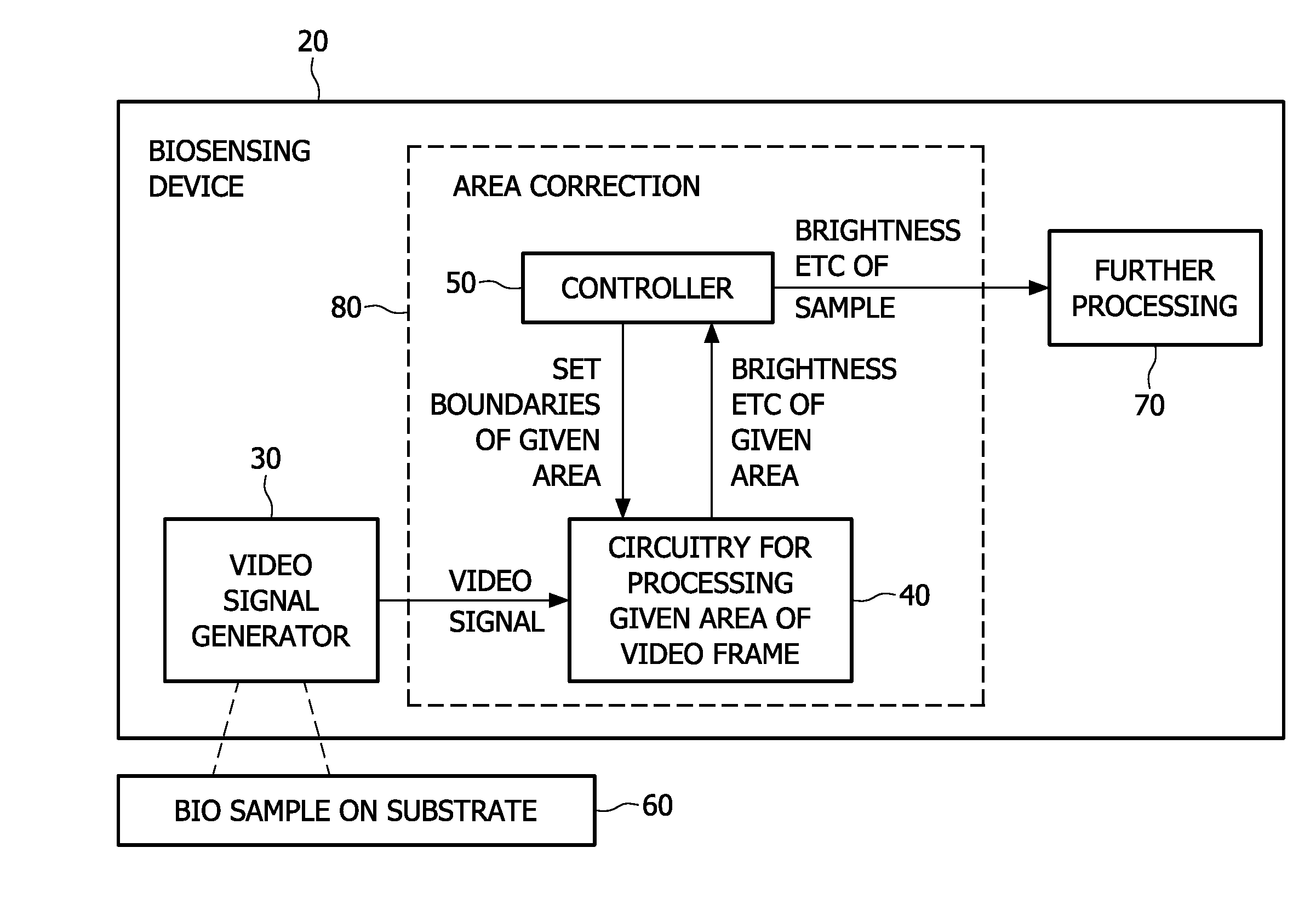
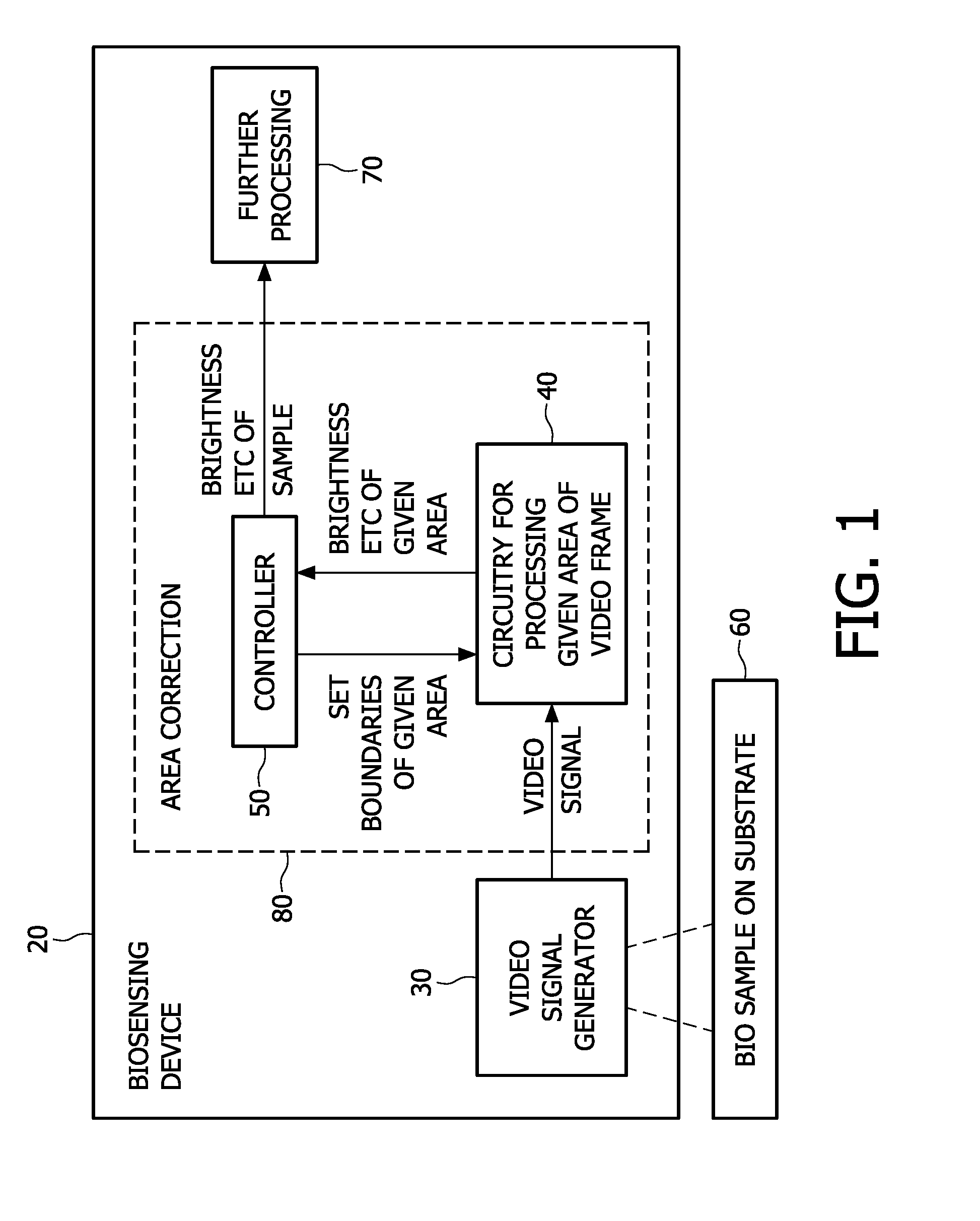
[0049]A first embodiment of the present invention is shown in FIG. 1. This shows a schematic view of a biosensing device 20 having a video signal generator 30 arranged to image a biosample 60 on a substrate. The video signal generator may be part of the biosensing device or it may be a separate apparatus for use with the biosensing device 20. The substrate can optionally be incorporated within the biosensing device, or be a separate cartridge or swab or any container for example.

[0050]An area correction part 80 of the device takes the video signal and has circuitry 40 for processing a given first area of each frame of video. For some applications a time sequence of brightness values is needed in order to interpret an assay event such as a chemical binding process correctly for example. In one embodiment, at least 10 frames per second should be processed, e.g. from a 752H×480V (CCD / CMOS) video camera. The circuitry outputs a brightness value of a given firs...

embodiment 1

FIG. 3 Correction for Binding-Spot Shape

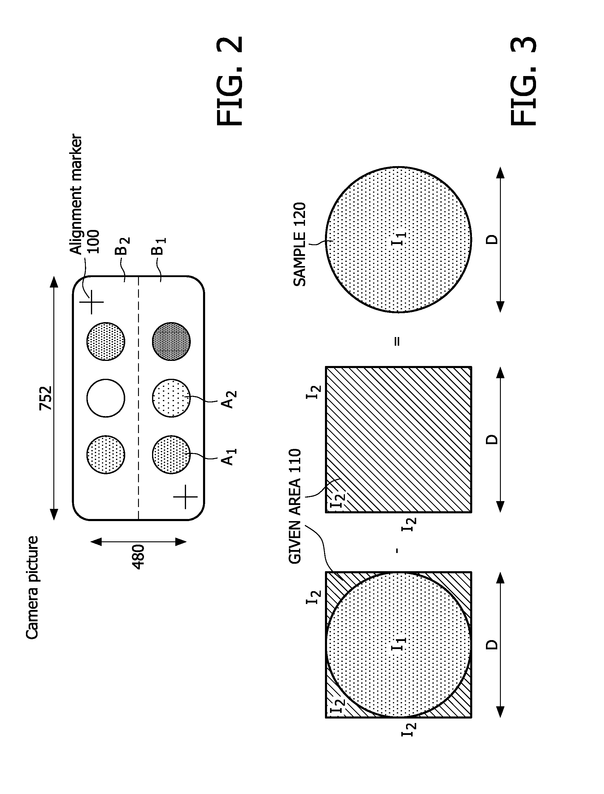
[0073]To reduce hardware complexity and power consumption, the assay locations, e.g. binding spots are measured by a suitable method, e.g. finding the brightness of a polygonal, e.g. rectangular given first area 110 (intensity I2) centred on the assay location, e.g. the spot (intensity I1) as shown in FIG. 3. As the assay locations, e.g. binding-spots are usually not rectangular, the measured light power of the rectangular first area does not reflect the correct information.

[0074]FIG. 3 shows a circular assay location, e.g. binding spot (dark shaded, intensity I1) from which the intensity is measured by measuring a polygonal e.g. rectangular given first area (diagonal shaded, intensity I2). As shown diagrammatically, in FIG. 3, the brightness of the assay location, e.g. spot in terms of the average light intensity can be found by subtracting the measurement of the same first area without the assay location, e.g. spot, from the measurement of ...


PUM


Abstract

A biosensing device for sensing brightness of a bio sample from frames of a video signal, has circuitry (40) arranged to receive the video signal and determine a brightness of a given area (110) of one or more of the frames in real time. A controller (50) adjusts boundaries of the given area, and uses the measures of brightness for different boundaries, to determine location of edges of the sample, then sets the boundaries according to the edges for subsequent measurements of brightness. By determining the brightness in real time, the given area can be adjusted in real time. By adjusting the given area based on real time assessments of brightness, various common errors or tolerances in sample shapes and locations can be compensated without the need for the software to carry out operations at pixel rates.

Description

[0001]This invention relates to biosensing devices, to image processing devices, and to corresponding methods and software. In particular, the invention relates to such devices for sensing brightness of a sample from an area of a frame of video signal.[0002]The ability to identify and / or separate biosamples such as cell sub-populations from a heterogeneous cell mixture is essential in many biomedical applications. Some methods exploit specific binding of antibodies to antigens on a cell surface to target a particular cell population. Examples of such methods are magnetically activated cell sorting (MACS), where antibody-functionalized magnetic beads are attached to the cells and sorted in a magnetic field, or fluorescence-activated cell sorting (FACS), where cells are labeled with fluorescent antibodies and separated by electrostatically deflecting charged liquid droplets containing the cells. Current FACS analyzers are very versatile instruments and allow cell separation on the bas...

Claims


Application Information

Patent Timeline
IPC IPC(8): H04N5/228
CPCG01N21/6456G01N2021/1765G06T7/0012G06T2207/30072G06T2207/10016G06T2207/10056G06T7/0083G06T7/12
Inventor KAHLMAN, JOSEPHUS ARNOLDUS HENRICUS MARIA
Owner KONINKLIJKE PHILIPS ELECTRONICS NV
Why Eureka
Try Eureka