Method for controlling a solenoid valve

a solenoid valve and valve actuation technology, applied in the direction of braking systems, process and machine control, instruments, etc., can solve the problems of valve triggering, pressure estimation and calibration procedure, and errors in estimation of brake pressure,

Active Publication Date: 2011-01-13
ROBERT BOSCH GMBH
View PDF9 Cites 14 Cited by
  • Summary
  • Abstract
  • Description
  • Claims
  • Application Information

AI Technical Summary

Benefits of technology

[0006]An object of the present invention is to provide an improved method for controlling a solenoid valve, in par

Problems solved by technology

Due to the variety of different methods, unambiguous switchover conditions between the different methods must be defined.
Therefore, valve triggering, pressure estimation and the calibration procedure are very complex.
Likewise, the dynamic response

Method used


Image

  • Method for controlling a solenoid valve
  • Method for controlling a solenoid valve
  • Method for controlling a solenoid valve

Examples


Embodiment Construction

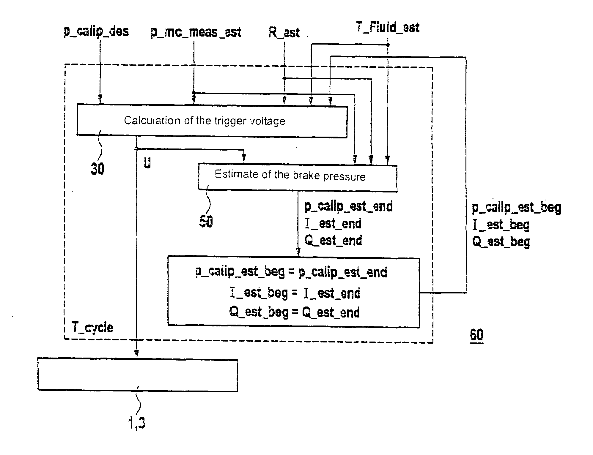
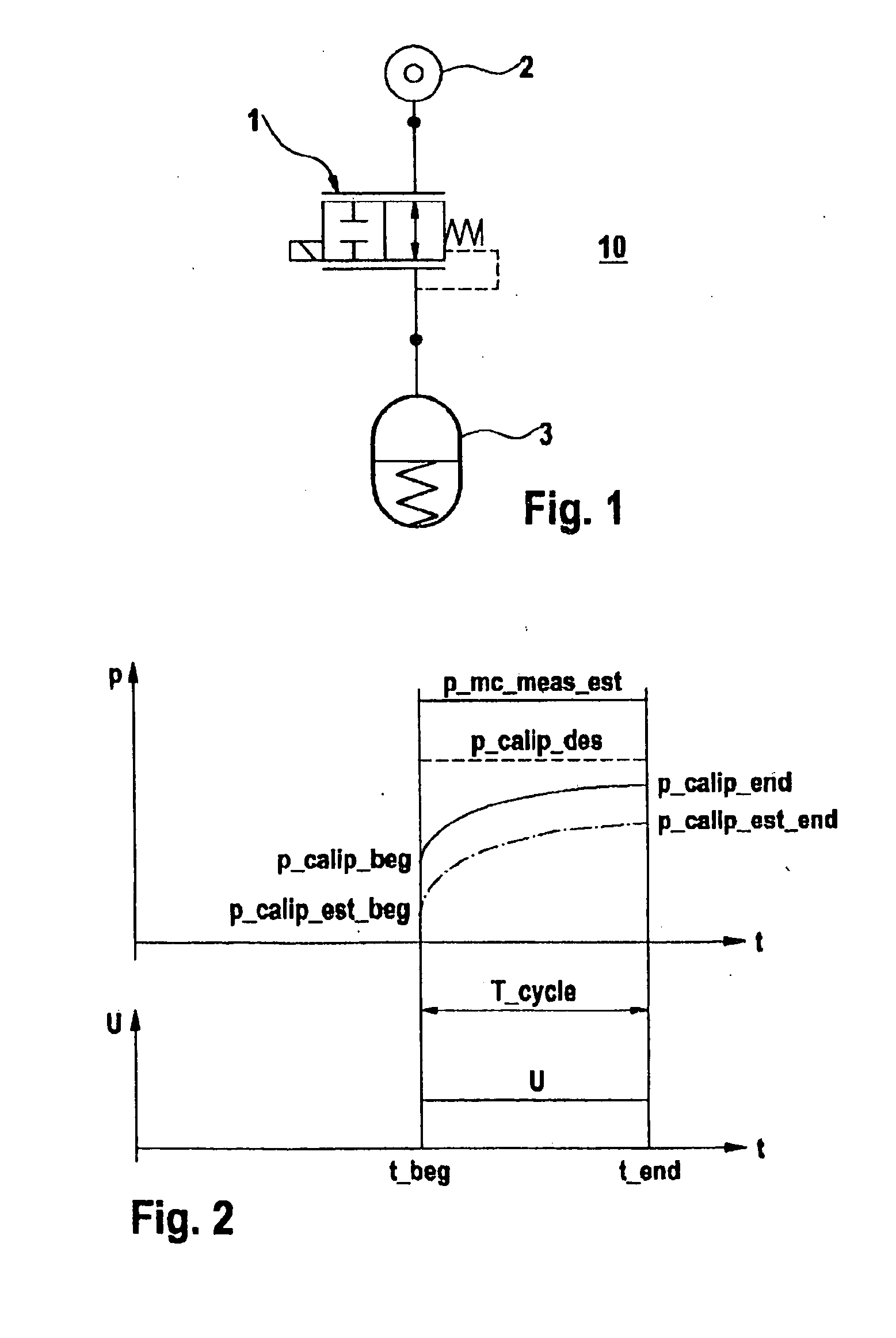
[0019]The present invention is explained below using the example of an ABS / ESP system for a motor vehicle, assuming a digital implementation having a fixed sampling time (cycle time). In a schematic and simplified diagram, FIG. 1 shows the essential components of the controlled system for the pressure build-up, including a proportional solenoid valve 1 as the control member, a main brake cylinder 2 as the pressure source and a brake caliper 3 as the accumulator. A dynamic model is used to calculate the coil voltage on proportional solenoid valve 1.

Model of the System

[0020]The control and estimation problem is first formulated below and then the calculation path for the coil voltage and the brake pressure is presented with the help of the model, on which the method according to the present invention is based. The equation system of the model for proportional solenoid valve 1 includes a differential equation for the coil having an inductance L and an ohmic resistance R:

It=1L(U-R·I)(1)...


PUM


Abstract

In a method for controlling a proportional solenoid valve in a hydraulic system, a model of the hydraulic system is formed, control cycles are predefined, and an estimate is made of the pressure prevailing in the hydraulic system at the end of the control cycle and of the coil current applied to the coil of the solenoid valve based on the variables prevailing at the start of the control cycle, the physical parameters of components of the hydraulic system, and the temperature of the hydraulic fluid.

Description

BACKGROUND OF THE INVENTION[0001]1. Field of the Invention[0002]The present invention relates to a method for controlling a solenoid valve, e.g., a proportional solenoid valve, which is used for controlling the pressure in a hydraulic system, such as ABS and / or ESP in a motor vehicle.[0003]2. Description of Related Art[0004]In implementation of vehicle dynamics control systems such as ABS, ESP, ASR and the like, a proportional solenoid valve is used for a targeted build-up of pressure or reduction in pressure in the hydraulic system. The hydraulic system may include, for example, a hydraulic brake circuit, a hydraulically operable clutch in an automatic transmission, hydraulic actuators for influencing driving dynamics or the like. Known controllers of a proportional solenoid valve for ABS / ESP systems assume either a strict steady-state behavior of the proportional solenoid valve (dp method), a strict switching behavior (quasi-switching method) or a linear valve behavior (LMV method...

Claims


Application Information

Patent Timeline
IPC IPC(8): B60T8/17G05D7/00
CPCB60T8/172B60T8/36B60T2270/308B60T2270/204B60T2270/14
Inventor RUBENBAUER, MICHAELLOLENKO, KOSTYANTYN
Owner ROBERT BOSCH GMBH
Why Eureka
Try Eureka