Photoresponsive gas-generating material, micropump and microfluid device

Active Publication Date: 2011-01-20
SEKISUI CHEM CO LTD
View PDF8 Cites 12 Cited by
  • Summary
  • Abstract
  • Description
  • Claims
  • Application Information

AI Technical Summary

Benefits of technology

[0043]According to the first aspect of the present invention, since the photoresponsive gas-generating material contains a photo-sensitive acid-generating agent and an acid-sensitive gas-generating agent, the photo-sensitive acid-generating agent is decomposed when irradiated with light and generates an acid. In addition, the acid reacts with the acid-sensitive gas-generating agent. Accordingly, it is possible to immediately generate gases from the acid-sensitive gas-generating agent. Therefore, the use of the photoresponsive gas-generating material of the present invention in a micropump of a microfluid device enables transportation of a microfluid and improvement of the liquid-transport efficiency.
[0044]According to the photoresponsive gas-generating material of the second aspect of the present invention, it is possible to effectively generate gases by irradiation with light. For example, when light energy required to decompose a 1-mol photo-sensit

Problems solved by technology

Micropumps of various types as disclosed in Patent Documents 1 to 4 has a complex structure, and thus reduction of their size is difficult.
In particular, the pumps described in Patent Documents 1 and 2, which have a diaphragm structure or a minute piston used therein, not only has difficulty in reduction of their size but also problematically cause pulsation of a microfluid to be transported due to their mechanical structures.
The hydrogen pump with a solid electrolyte used therein of Patent Document 4 has disadvantages that assembling process

Method used


Image

  • Photoresponsive gas-generating material, micropump and microfluid device
  • Photoresponsive gas-generating material, micropump and microfluid device
  • Photoresponsive gas-generating material, micropump and microfluid device

Examples


first embodiment

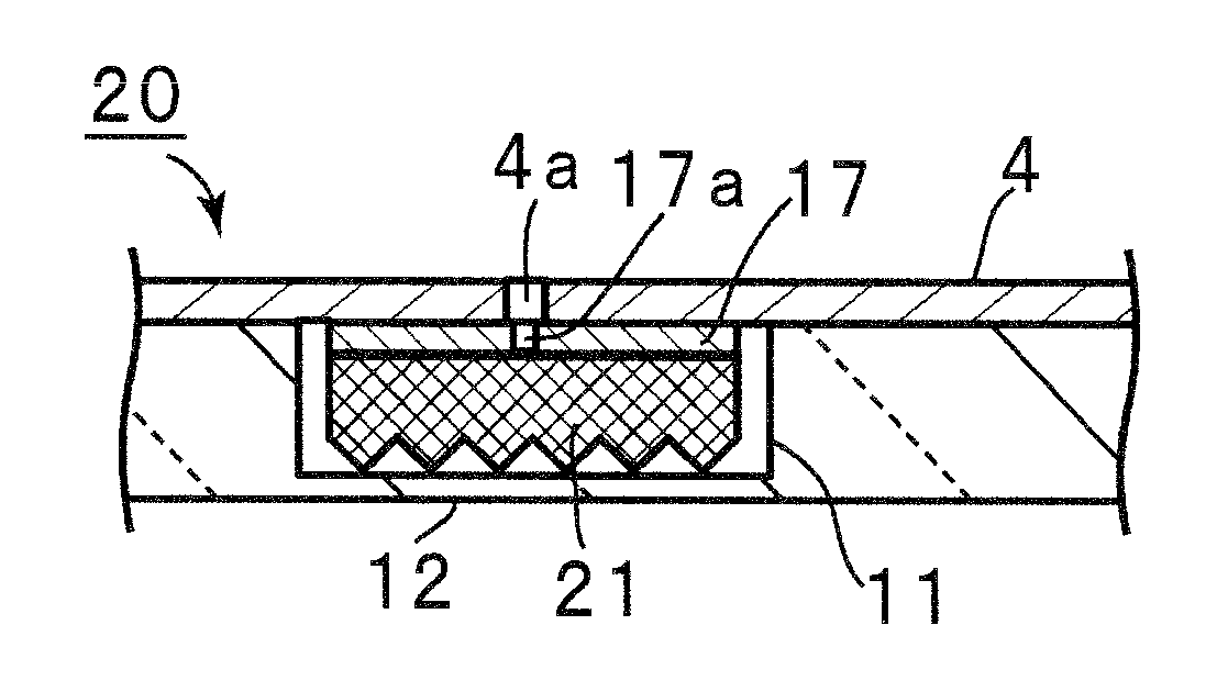
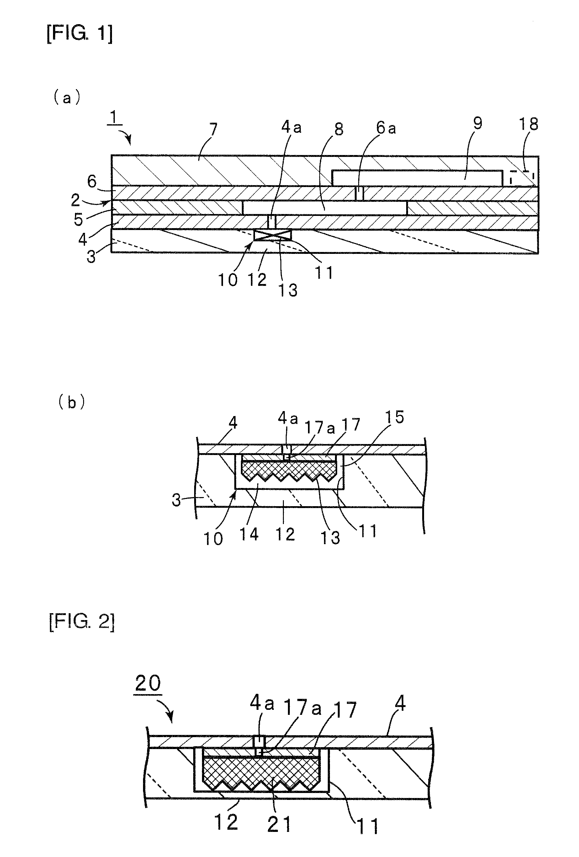
[0210]FIG. 1 (a) is a schematic front cross-sectional view of a microfluid device provided with a micropump of the first embodiment of the present invention, and 1(b) is an enlarged partial front cross-sectional view illustrating the structure of the micropump.

[0211]As shown in FIG. 1 (a), a microfluid device 1 has a substrate 2 having a plurality of plates laminated on one another. The substrate 2 has a base plate 3, intermediate plates 4 to 6 laminated on the base plate 3, and a top plate 7 laminated on the intermediate plate 6. The lamination structure of the substrate 2 is not limited to this.

[0212]A plurality of fine channels 8 and 9 are formed in the substrate 2. The fine channel 9 is connected to a reagent storage unit and an analyte feeding unit although they are not shown in the figures. The fine channel 8 is connected to a micropump chamber 10. As shown in FIGS. 1 (a) and (b), the micropump chamber 10 is formed in the substrate 2. More specifically, in the present embodime...

second embodiment

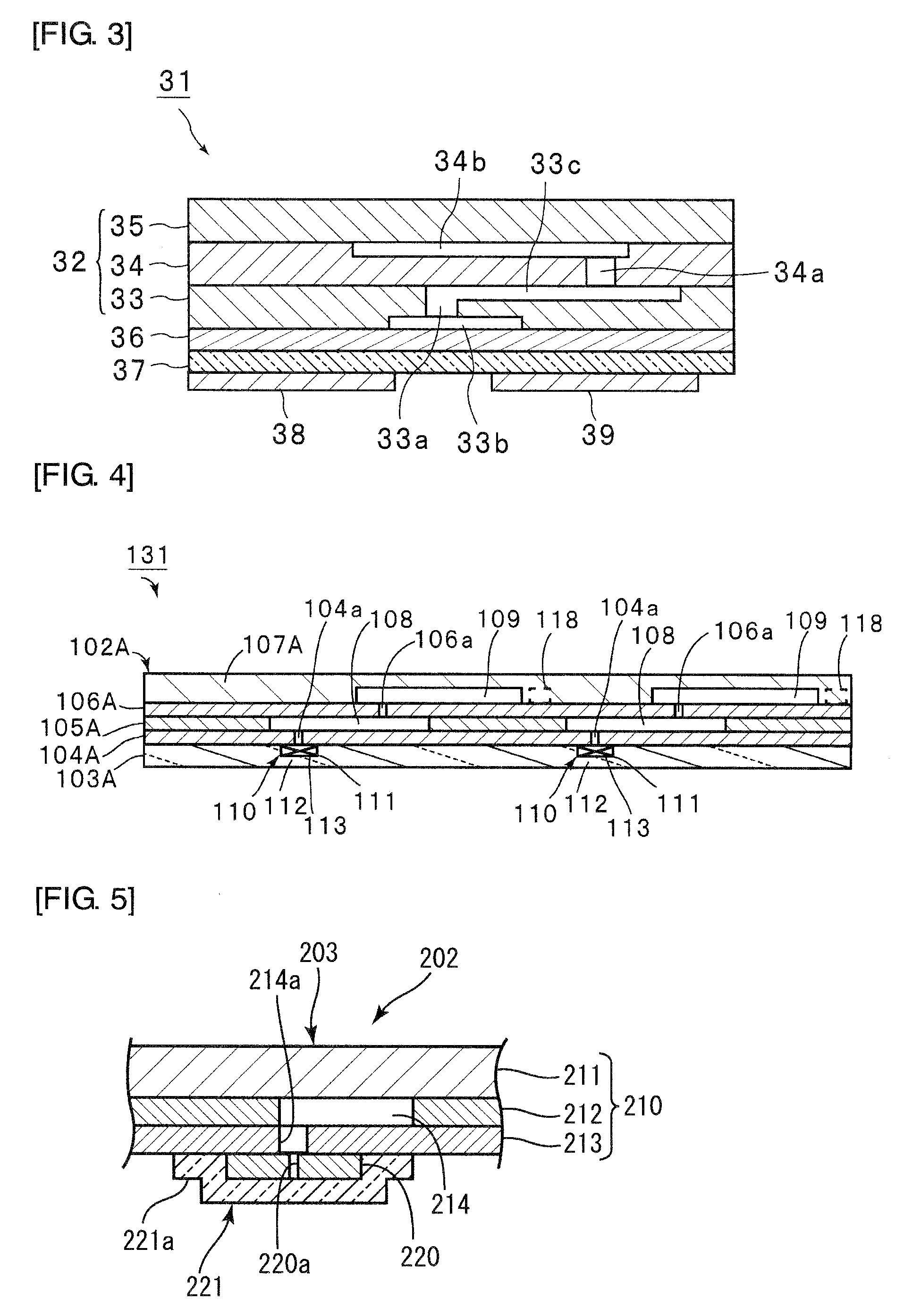
[0241]FIG. 3 is a schematic front cross-sectional view of a microfluid device of the second embodiment of the present invention.

[0242]As shown in FIG. 3, a microfluid device 31 has a substrate 32. The substrate 32 is formed by laminating a plurality of plates 33 to 35. Specifically, the intermediate plate 34 and the top plate 35 are laminated on the base plate 33. The base plate 33, the intermediate plate 34, and the top plate 35 of the substrate 32 may be formed using the same materials as the substrate materials of the first embodiment. A groove 33b is formed on the lower surface of the base plate 33 to be connected to a through hole 33a in the base plate 33. A groove 33c is formed on the upper surface of the base plate 33 to be connected to the upper end of the through hole 33a. A through hole 34a and a groove 34b connected to the upper end of the through hole 34a are formed in intermediate plate 34. The groove 34b is closed by the top plate 35.

[0243]A film-form photoresponsive g...

third embodiment

[0250]FIG. 4 is a front cross-sectional view of a micro chemical chip of a microfluid device of the third embodiment of the present invention.

[0251]The micro chemical chip 131 shown in FIG. 4 has a structure in which two of the microfluid devices of the first embodiment are arranged. The micro chemical chip 131 has a base plate 103A as a first plate having two micropumps 110 built therein.

[0252]At least two gas-generating chambers 111 are formed in the base plate 103A. Optical windows 112 are formed on one surface of the base plate 103A to face the two gas-generating chambers 111, respectively. The two gas-generating chambers 111 each house a supporting member having a photoresponsive gas-generating material 113 attached thereto. Also in the micro chemical chip 131 shown in FIG. 4, a photoresponsive gas-generating fine particulate material and / or a photoresponsive gas-generating film may be housed in the gas-generating chambers 111 instead of or in addition to the photoresponsive ga...


PUM


Abstract

The present invention provides a photoresponsive gas-generating material that is to be used in a micropump of a microfluid device having fine channels formed therein, and is capable of effectively generating gases for transporting a microfluid in response to light irradiation and transporting the microfluid at an improved transport efficiency. The present invention also provides a micropump incorporating the photoresponsive gas-generating material.
A photoresponsive gas-generating material 13 is to be used in a micropump having fine channels formed in a substrate, and comprises a photo-sensitive acid-generating agent and an acid-sensitive gas-generating agent, and a micropump 10 has the photoresponsive gas-generating material 13 housed therein.

Description

TECHNICAL FIELD[0001]The present invention relates to a photoresponsive gas-generating material used in a micropump of a microfluid device with fine channels formed therein, and more specifically an photoresponsive gas-generating material capable of generating gases for transporting a microfluid in response to light irradiation and transporting the microfluid at an improved transport efficiency. The present invention also relates to a micropump and a microfluid device incorporating the photoresponsive gas-generating material.BACKGROUND ART[0002]In recent years, the size of analysis devices of various fields has been reduced. For example, a smaller-sized crystal inspection device is strongly demanded for bedside diagnosis in which diagnosis is made near a patient. Smaller-sized analysis devices are also strongly demanded for analysis of environmental pollutants in the air, water, or soil because these devices are used outdoors for such analysis.[0003]Microfluid devices attract attent...

Claims


Application Information

Patent Timeline
IPC IPC(8): B01L3/00C06B45/10C06B25/04C06B45/12
CPCB01L3/50273F04B19/006B01L2400/046B01L2300/0887Y10T137/2082B01J7/00B01J19/00B81B1/00F04F1/18
Inventor FUKUOKA, MASATERUYAMAMOTO, KAZUKIAKAGI, YOSHINORIFUKUI, HIROJI
Owner SEKISUI CHEM CO LTD
Why Eureka
Try Eureka