Method of Modifying Target Region in Host DNA and Selectable Marker Cassette

a technology of target region and host dna, which is applied in the field of modifying target region in host dna and relating to selectable marker cassette, can solve the problems of insufficient improvement of operational efficiency, difficult to introduce large-size dna segment or lethal gene into the desired region of host dna, and the method is not entirely satisfactory for improving operational efficiency. the effect of efficiency improvemen

Active Publication Date: 2011-01-20
KAO CORP
View PDF0 Cites 1 Cited by
  • Summary
  • Abstract
  • Description
  • Claims
  • Application Information

AI Technical Summary

Benefits of technology

[0038]According to the methods of the present invention, it is possible to modify the desired region in the host DNA with a simple procedure.
[0039]According to the present invention, neither the first selectable marker gene nor second selectable marker gene used in the modification process (including the deleting process and the replacing process) remain in the host DNA after modification. Accordingly, it is possible to prepare a desired transformant without limiting the range of the selectable marker genes that can be used. In particular when a plurality of regions in the host DNA are modified, the modifying process according to the present invention can be much simplified, compared with that by the conventional gene modification method that the selectable marker gene remains in the host, because any selectable marker gene can be used without restriction. In addition to the selectable marker gene, according to the present invention, the other regions (such as first homologous recombination region, promoter sequence, and the like) used in the

Problems solved by technology

As described above, the conventional genetic manipulation method for modifying a host DNA and obtaining a transformant has a problem that a selectable marker is left in the transformant.
Thus, the method is not entirely satisfactory for improvement of operational efficiency.
In the conventional

Method used


Image

  • Method of Modifying Target Region in Host DNA and Selectable Marker Cassette
  • Method of Modifying Target Region in Host DNA and Selectable Marker Cassette
  • Method of Modifying Target Region in Host DNA and Selectable Marker Cassette

Examples


example 1

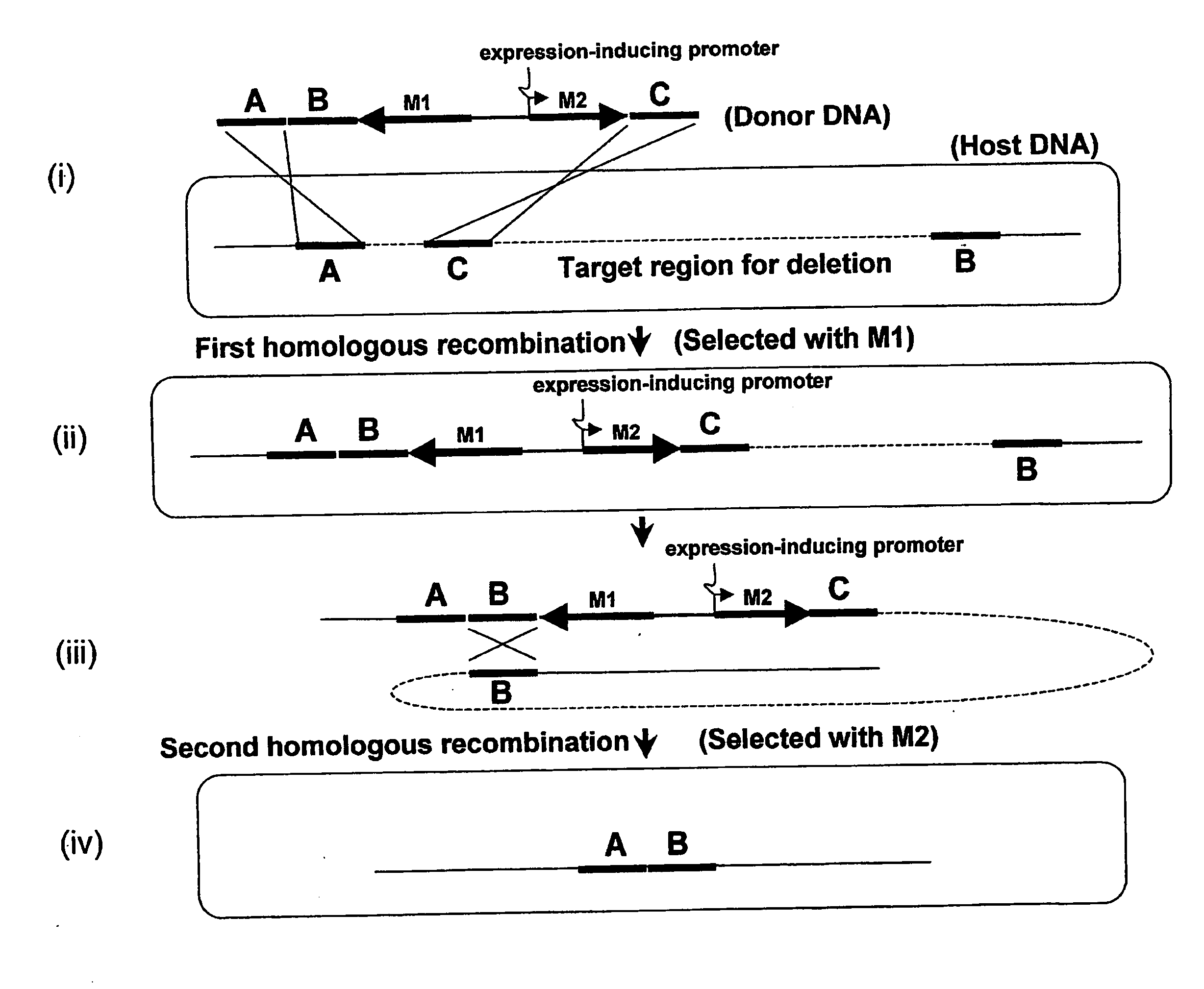
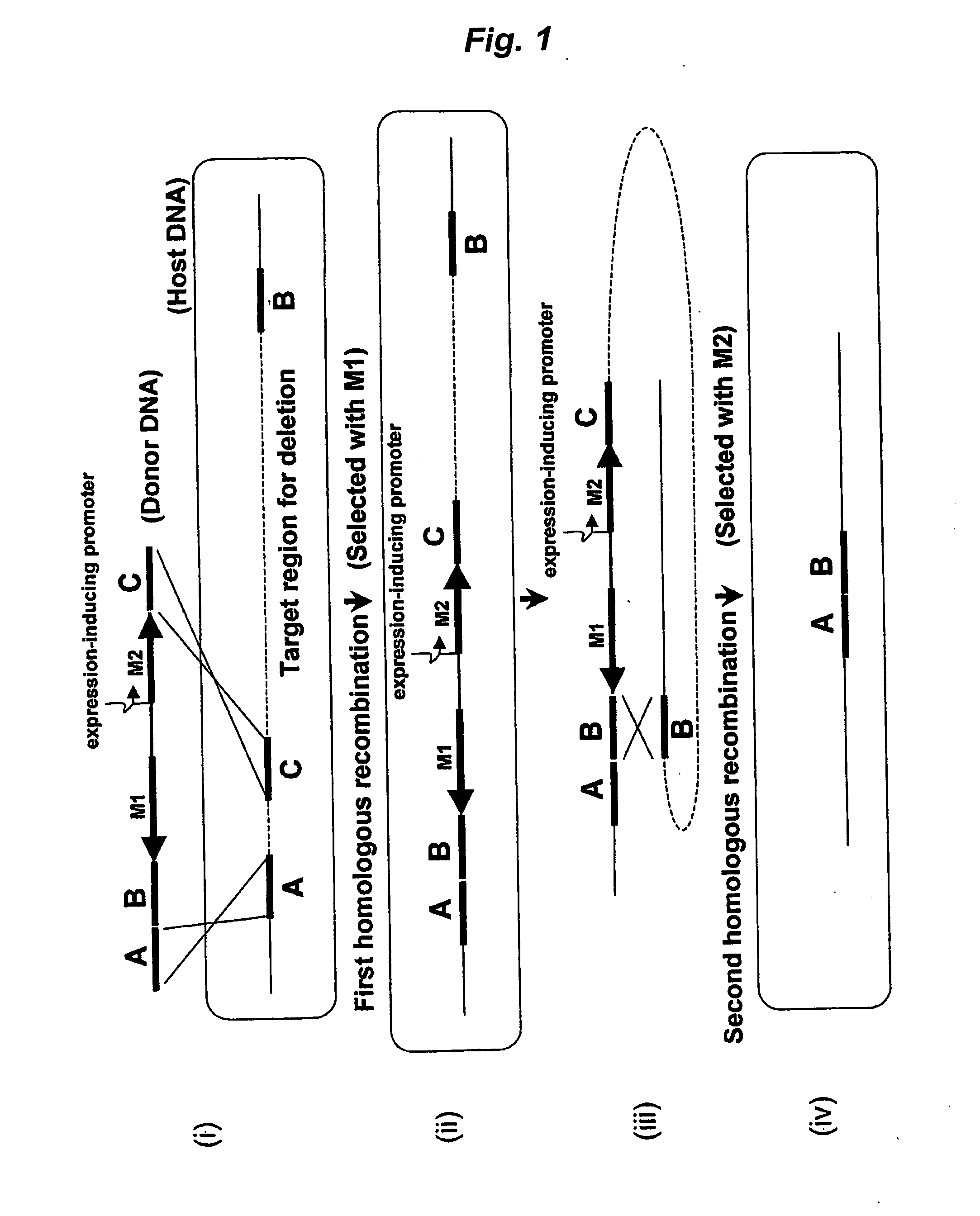
[0127]In the present Example, the pro5 region (20,485 bp), which is the region from 1,879,258 bp to 1,899,742 bp on the genome of Bacillus subtilis 168, was deleted as the target region for deletion. The sequences of the primers used in the present Example are shown in Table 1. The flow diagrams of the present Example are shown in FIG. 5 and FIG. 6.

TABLE 1Primer sequencesSEQ IDPrimerNucleotide sequenceNO:pO2HC-lacFCTCACATTAATTGCGTTGCG3pO2HC-lacRCTTACCATAGTTAATTTCTCCTCTTTAATG4chpA-FGAAATTAACTATGGTAAGCCGATACGTACC5chpA-RCGCGGATCCTACCCAATCAGTACGTTAATTTTG6APNC-FCGACAGCGGAATTGACTCAAGC7pro5-DF1GAGCAAAGAAGAGCGCATGG8pro5-DR1CAGCATGGAGAAGATTTCAACGTAATTATGG9pro5-DF2CGTTGAAATCTTCTCCATGCTGTGTGATTGATC10pro5-DR2CTGATTGGGTAGGATCCGCGATATTTATCGACGAACTCAGAT11pro5-IFGAGTCAATTCCGCTGTCGATCAATCACAATGGAGGAC12pro5-IRTACGTAAGTATCAGCACAGG13pro5-checkFCTGCAAACCCATACCTTGCAC14pro5-checkRCATCACTAAATCTCTTAAACGTC15

[0128]First, mutant strains, Bacillus subtilis 168 (aprE::spec, lacl, Pspac-chpA) and Bacillus subtili...

example 2

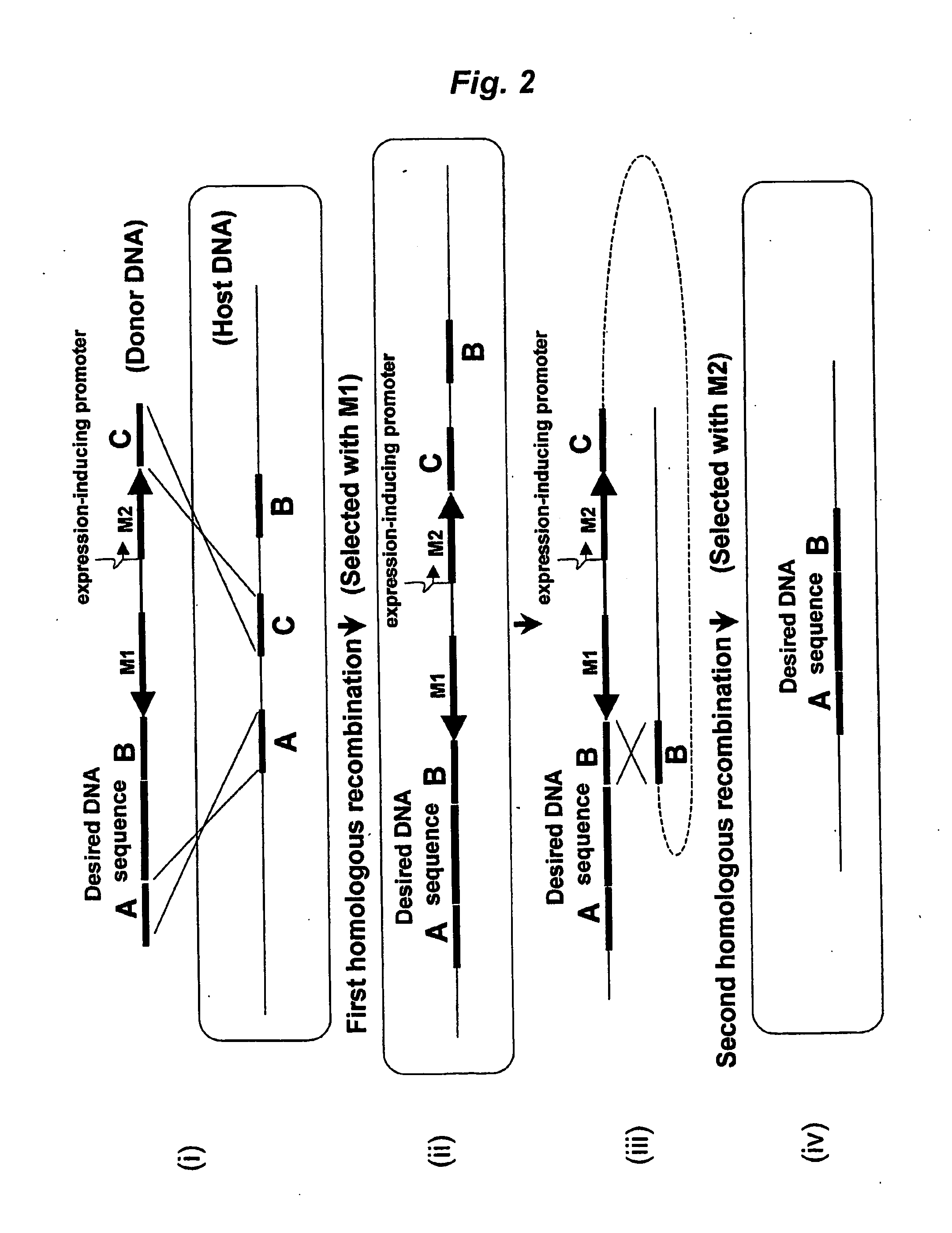
[0141]In the present Example, the flgB-fliH region (4,708 bp) corresponding to 1,690,526 bp to 1,695,233 bp in the genome of Bacillus subtilis 168 was used as the desired DNA sequence, and the DNA sequence was inserted into the target region for replacement in the host DNA. The sequences of the primers used in the present Example are shown in Table 2. The flow diagram of the present Example is shown in FIG. 7.

TABLE 2Primer sequencesSEQ IDPrimerNucleotide sequenceNO:chpA-RCGCGGATCCTACCCAATCAGTACGTTAATTTTG6APNC-FCGACAGCGGAATTGACTCAAGC7flgB-FGCGTTCAGCAACATGTCTGTTTCTCGACAAGGATATTGAGG16flgB-RGCAGCTGCTTGTACGTTGATCCGTACCGTTTATACGAGTC17aprEclone-fFTCTGATGTCMGCTTGGCG18aprEclone-fRACAGACATGTTGCTGAACGC19aprEclone-bFATCAACGTACAAGCAGCTGC20aprEclone-bRCTGATTGGGTAGGATCCGCGCCATTATGTCATGAAGCACG21aprEclone-mFGAGTCAATTCCGCTGTCGTTCTCACGGTACGCATGTAG22aprEclone-mRAGAATTAACGCTGCTGCTCC23aprEclone-checkFTTGCAAATCGGATGCCTGTC24aprEclone-checkRTATTGTGGGATACGACGCTG25

[0142]By using the chromosomal DNA of the str...


PUM

PropertyMeasurementUnit
Electrical resistanceaaaaaaaaaa
Recombination enthalpyaaaaaaaaaa

Abstract

A method of modifying a target region in a host DNA using a donor DNA:
    • wherein the donor DNA having regions homologous to a 5′-side region outside of the target region in the host DNA, a 3′-side region outside of the target region in the host DNA and a first homologous recombination region inside of the target region in the host DNA, respectively, in this order, and further having a first selectable marker gene, an expression-inducing promoter and a second selectable marker gene expressed under the control of the expression-inducing promoter between the region homologous to the 3′-side region and the region homologous to the first homologous recombination region;
  • which method has the steps of:
    • a first step of performing homologous recombination between the donor DNA and the host DNA at the regions of the 5′-side region and the first homologous recombination region, to conduct selection of a host integrated with the donor DNA based on expression of the first selectable marker gene; and
    • a second step of performing homologous recombination, within the host DNA integrated with the donor DNA by the first step, between two regions of the 3′-side region derived from the host DNA and the 3′-side region derived from the donor DNA, to conduct selection of a host whose target region is modified based on expression of the second selectable marker gene under an expression-inducing condition for the expression-inducing promoter: and a selectable marker cassette for use in the method.

Description

TECHNICAL FIELD[0001]The present invention relates to a method of modifying a target region in a host DNA and relates to a selectable marker cassette.BACKGROUND ART[0002]Drug-resistance genes have been used as a means for artificial selection of transformants in the genetic engineering field. Specifically, a desired transformant can be selected based on a drug-resistance gene whose expression confers drug resistance. Not only the drug-resistance genes but also, for example, auxotrophic genes are used as means for selecting transformants. These genes usable for selecting transformants are generally called selectable markers (selectable marker genes).[0003]Selectable marker genes are useful for selecting transformants. However, such a selectable marker gene, depending on its kind, unfavorably exhibits adverse effects on the environment, such as biological pollution of a wild-type microorganism by the selectable marker gene, if the selectable marker gene remains in a host cell. In addi...

Claims


Application Information

Patent Timeline
IPC IPC(8): C12N15/87C12N15/63
CPCC12N15/1082C12N15/102
Inventor ARA, KATSUTOSHIMORIMOTO, TAKUYAOGASAWARA, NAOTAKE
Owner KAO CORP
Why Eureka
Try Eureka