Drive Circuit

a drive circuit and circuit technology, applied in the direction of ac-dc conversion, electric variable regulation, instruments, etc., can solve the problems of significant gate capacitance, significant power consumption, and significant standby power of the inverter itself, so as to reduce the gate drive power and improve the efficiency of the inverter

Active Publication Date: 2011-01-27
POWER CONCEPTS NZ
View PDF31 Cites 34 Cited by
  • Summary
  • Abstract
  • Description
  • Claims
  • Application Information

AI Technical Summary

Benefits of technology

[0016]Advantageously, the drive circuit might reduce the inverter standby power consumption over existing circuits.
[0032]Preferably, the inverter further comprises a controller adapted to vary one or both input voltages received by the first and second half bridge circuits to reduce the gate drive power when there is little or no AC power being drawn from the inverter by decreasing one or both input voltages, and to improve the efficiency of the inverter when there is significant AC power being drawn by increasing one or both input voltages.

Problems solved by technology

When this is done the standby power of the inverter itself can become significant, especially in installations where there is a limited amount of power, such as those using solar panels, or in installations where the inverter is run from a storage battery that is recharged periodically and must supply all the installation's power between each recharge.
Most of the standby power is the power required to operate the circuitry of the inverter, so this power is also being consumed even when there is power passing through the inverter.
It is likely that these devices will also have significant gate capacitances.
Many gate drive circuits are not able to provide this range of periods.
If the signal coupled to the gate is large enough to turn the device on then both devices will be on at the same time and the resulting short circuit will cause a large amount of current to flow through the devices, in many cases resulting in the destruction of both devices.
Conversely, the voltages present in the high voltage side of the inverter is classed as hazardous and must be provided with a prescribed amount of insulation and isolation from any conductor that can be touched by a person in order to meet the relevant electrical safety regulations.
This has the potential to cause a large current to flow through the winding on the high voltage side of the gate transformer, potentially over-heating it and melting the insulation between the high voltage side and the control circuit side of the transformer.
Thus it is necessary for each gate drive circuit to be as simple as possible or else the cost of and the space required by all the gate drive circuits together would be unacceptable.
Often this leads to a separate power supply being required for each power switching device.
These factors often lead to a very complex design if gate drive circuits requiring separate power supplies are used.
However, all these circuits require one or more power supplies to be connected to the circuit containing the capacitor and are therefore not suitable for producing a simple isolated gate drive circuit for a low standby power DC to AC inverter.
However, none of these circuits use resonance to reduce the power required to repeatedly charge and discharge the gate capacitance.

Method used


Image

  • Drive Circuit
  • Drive Circuit
  • Drive Circuit

Examples


second embodiment

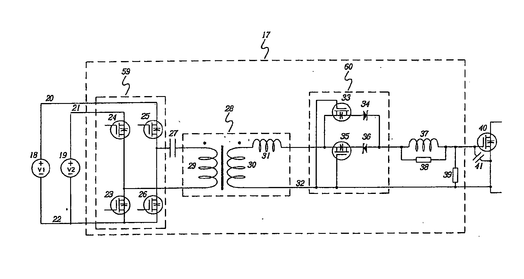
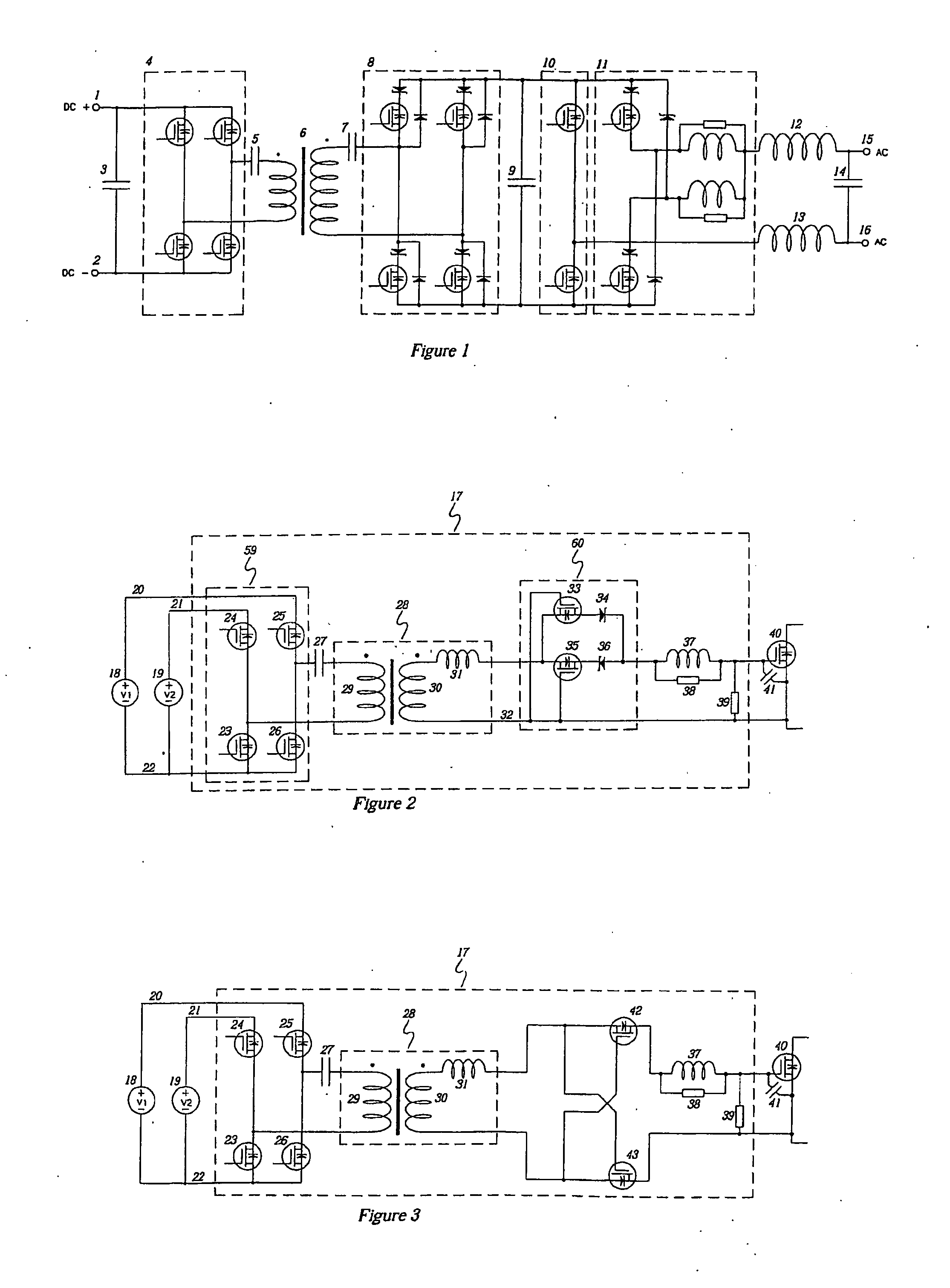
[0068]the drive circuit 17 for a control input of a voltage controlled power switching device (or voltage controlled switch) is shown in FIG. 3. This differs from the embodiment shown in FIG. 2 only in the form of the transition selection circuit. Only the operation of the transition selection circuit will be described as the rest of the circuit operates identically to the embodiment shown in FIG. 2.

[0069]For a positive transition the dot end of the secondary winding 30 of the transformer 28 is positive with respect to its non-dot end. This means that the first n-channel MOSFET 42 will be held off while the second n-channel MOSFET 43 will be turned on. Current will flow through the body diode of the first n-channel MOSFET 42 and return via the second n-channel MOSFET 43.

[0070]For a negative transition the dot end of the secondary winding 30 of the transformer 28 is negative with respect to its non-dot end. This means that the first n-channel MOSFET 42 will be turned on while the sec...

third embodiment

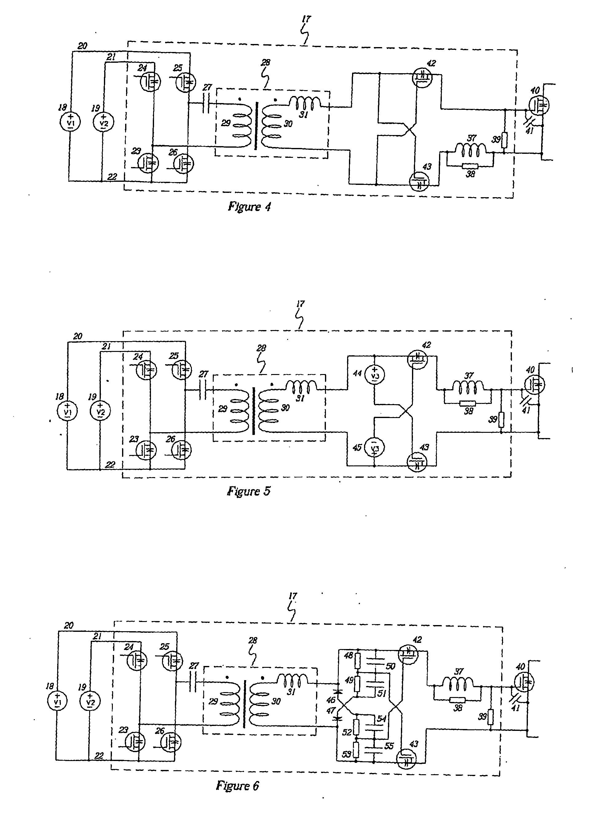
[0072]the drive circuit 17 for a control input of a voltage controlled power switching device (or voltage controlled switch) is shown in FIG. 4. This differs from the embodiment shown in FIG. 3 only in that it shows an alternative location for the resonating inductor 37 and its associated damping resistor 38.

fourth embodiment

[0073]the drive circuit 17 for a control input of a voltage controlled power switching device (or voltage controlled switch) is shown in FIG. 5. This is the same as the embodiment shown in FIG. 3 with the addition of a third voltage source 44 and a fourth voltage source 45. The third voltage source 44 is connected in series with the gate of the n-channel MOSFET 43. The fourth voltage source 45 is connected in series with the gate of the n-channel MOSFET 42. The purpose of the third and fourth voltage sources is to provide reverse bias to the gates of the MOSFETs they are connected to in order to prevent the MOSFETs from being turned on by ringing superimposed on the voltage pulses produced at the secondary winding 30 of the transformer 28. At the end of a positive transition when the voltage produced at the secondary winding 30 of the transformer 28 returns to close to zero, it is likely to ring or overshoot so that the dot end of the winding becomes negative with respect to the non...


PUM


Abstract

The present invention relates to a DC to AC inverter comprising a plurality of voltage controlled switching devices, where one or more of the voltage controlled switching devices is driven by a drive circuit comprising: a bridge switching circuit (59), a transformer (28) with a primary winding (29) and a secondary-winding (30), a transition selection circuit (60) coupled to a control terminal of a respective voltage controlled switching device (40) of the inverter, at least one inductance (37) that forms at least one resonant circuit with the input capacitance (41) of the control terminal, wherein the bridge switching circuit (59) can be operated to generate drive pulses via the selection circuit (60) to operate the respective voltage controlled switching device (40).

Description

FIELD OF THE INVENTION[0001]The present invention relates to a circuit for reducing the standby power of DC to AC inverters that utilise voltage controlled power switching devices.BACKGROUND OF THE INVENTION[0002]There is increasing use being made of DC to AC inverters as a source of power for mains appliances, either in remote locations that do not have a connection to a mains supply grid, as part of an un-interruptible power supply which provides mains power in the event of a sudden interruption in the supply of grid connected power, or to connect sources of renewable energy such as wind or solar to the grid. In remote power applications it has been common for inverters to only be switched on when there is a need to operate a mains powered appliance. However, many mains appliances are now designed to operate in a standby mode when not actively being used. An example of this is a video recorder which goes into a low power standby mode while it is waiting to start recording a progra...

Claims


Application Information

Patent Timeline
Patent Type & Authority Applications(United States)
IPC IPC(8): H02M7/5387
CPCH02M1/08H03K2217/009H03K17/691H02M7/48
Inventor FOTHERBY, CHRISTOPHER WILLIAM
Owner POWER CONCEPTS NZ
Why Eureka
Try Eureka