
Tailored pulse burst

a pulse burst and pulse technology, applied in the field of lasers and optical amplifiers, can solve the problems of cumbersome implementation and high cost of external modulators and internal q-switches, and achieve the effects of minimizing recovery time, minimizing delay, and effectively suppressing the first puls

Active Publication Date: 2011-01-27
IPG PHOTONICS CORP
View PDF4 Cites 79 Cited by
  • Summary
  • Abstract
  • Description
  • Claims
  • Application Information

AI Technical Summary

Benefits of technology

[0039]Phase-matching refers to the technique used in a multiwave nonlinear optical process to enhance the distance over which the coherent transfer of energy between the waves is possible. For example, a three-wave process is said to be phase-matched when k1+k2=k3, where ki is the wave vector of the ith wave participating in the process. In frequency doubling, e.g., the process is most efficient when the fundamental and the second harmonic phase velocities are matched. Typically the phase-matching condition is achieved by careful selection of the optical wavelength, polarization state, and propagation direction in the non-linear material.
[0102]Embodiments of the present invention eliminate the need for cumbersome and expensive equipment that can accommodate high output powers and allow an unprecedented level of control in material processing applications. In the context of laser drilling and machining applications, this allows more energy efficient material removal and improves processing speed and throughput.

Problems solved by technology

However, external modulators and internal Q-switches are both cumbersome and expensive to implement.

Method used


Image

  • Tailored pulse burst
  • Tailored pulse burst
  • Tailored pulse burst

Examples


Embodiment Construction

er amplifier output for a tailored pulse burst followed by a flat topped pulse burst, linear vertical scale.

[0013]FIG. 9 is a schematic diagram of an electronic control system for generating pulse bursts according to a preferred embodiment of the present invention.

DESCRIPTION OF THE SPECIFIC EMBODIMENTS

[0014]Although the following detailed description contains many specific details for the purposes of illustration, anyone of ordinary skill in the art will appreciate that many variations and alterations to the following details are within the scope of the invention. Accordingly, the exemplary embodiments of the invention described below are set forth without any loss of generality to, and without imposing limitations upon, the claimed invention.

[0015]Glossary:

[0016]As used herein:

[0017]Beam splitter refers to an optical device capable of splitting a beam of light into two or more parts.

[0018]Brillouin scattering refers to a nonlinear optical phenomenon involving spontaneous scatterin...


PUM

PropertyMeasurementUnit
vacuum wavelengthaaaaaaaaaa
vacuum wavelengthsaaaaaaaaaa

Abstract

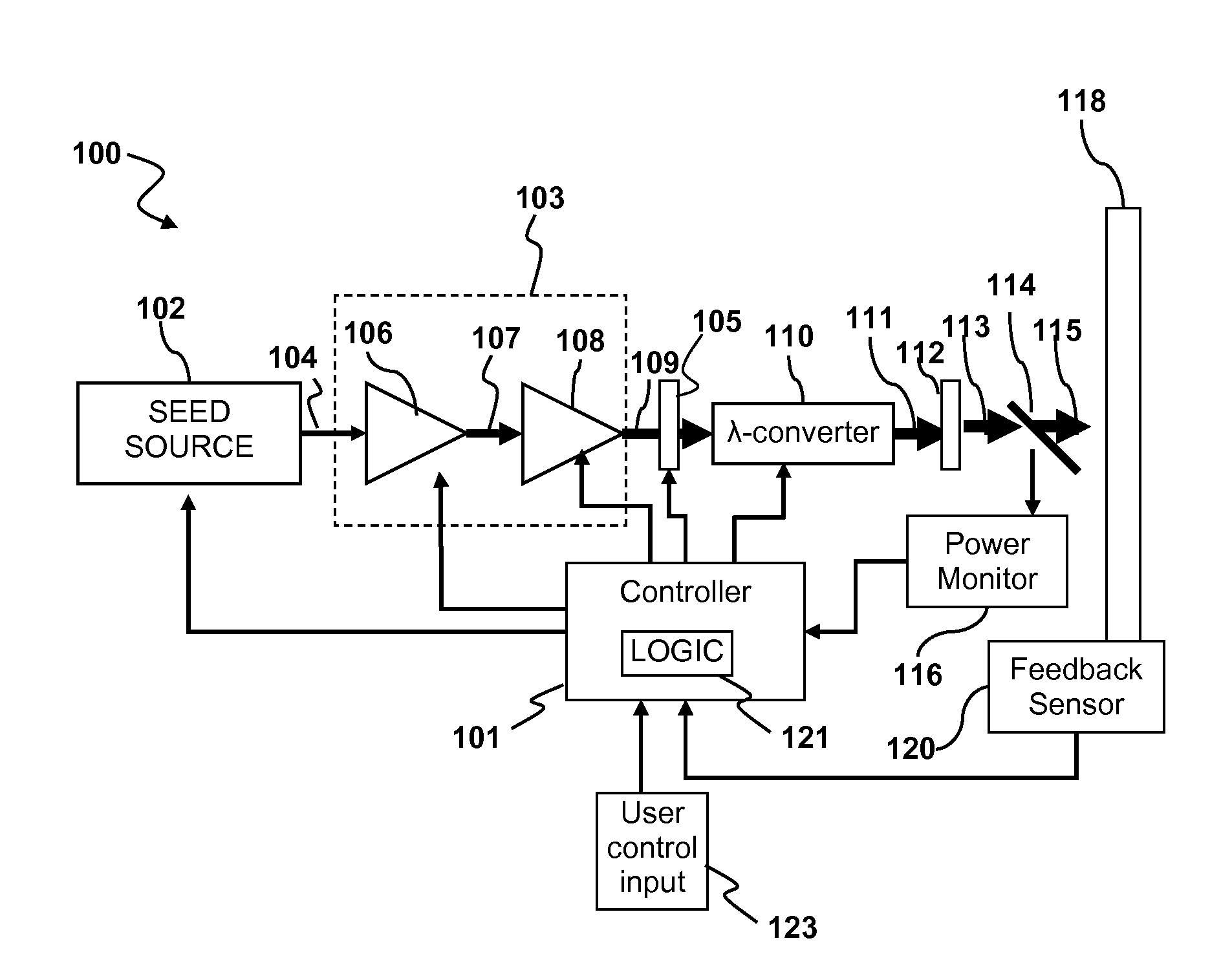
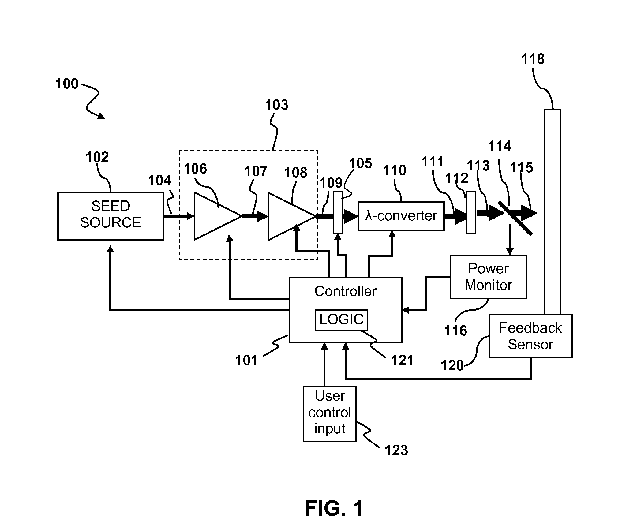
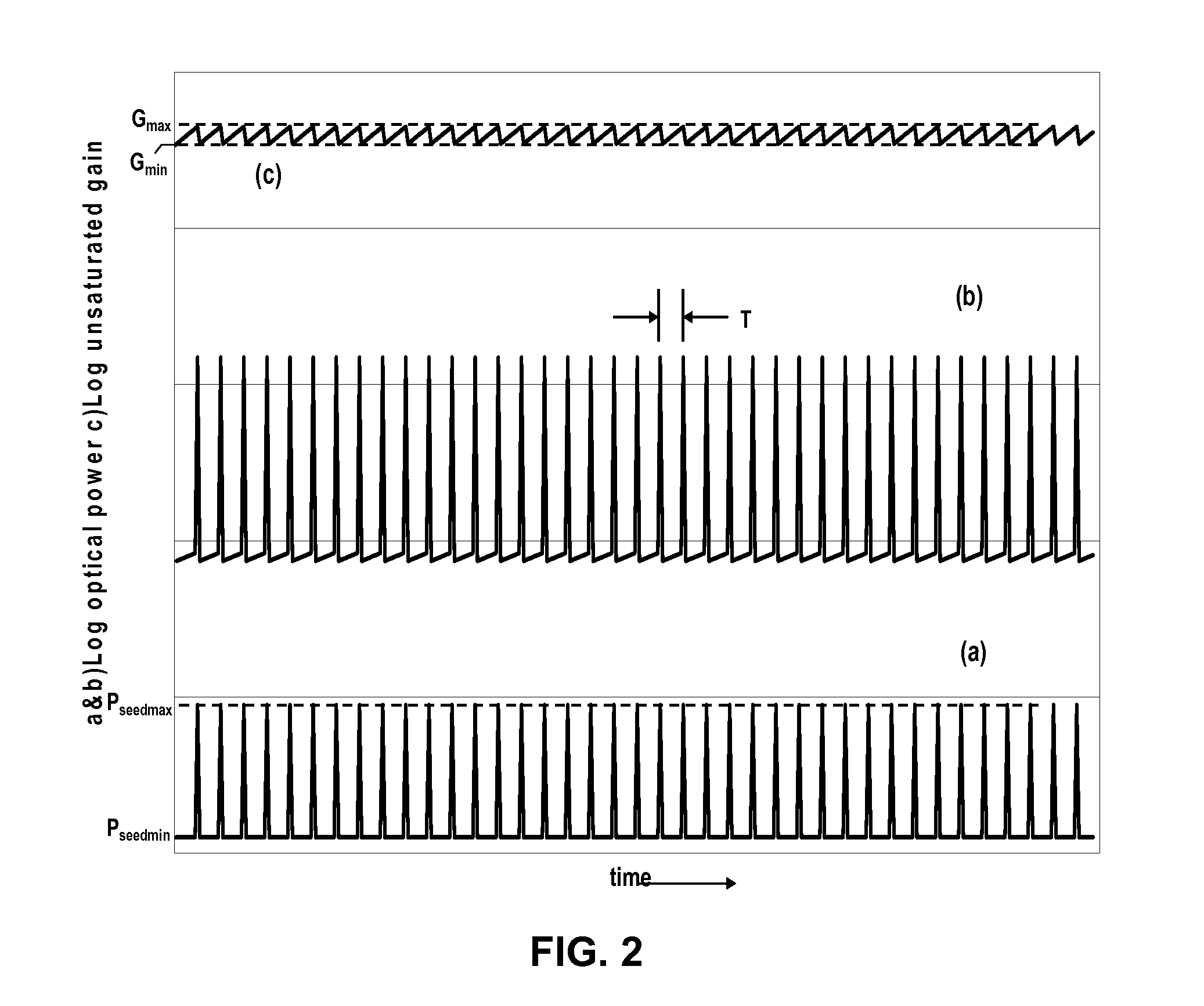
Output pulses from an optical system having a seed source and an optical amplifier coupled to the seed source may be controlled by controlling a power of a seed signal from the seed source. The seed signal may be varied between a minimum value and a maximum value in a way that the seed signal exhibits one or more pulse bursts. Each pulse burst may contain one or more pulses. During an inter-pulse period between successive pulses within a pulse burst or between successive pulse bursts, the power of the seed signal may be adjusted to an intermediate value that is greater than the minimum value and less than the maximum value. The intermediate value is chosen to control a gain in the optical amplifier such that a pulse or pulse burst that follows the period exhibits a desired behavior.

Description

FIELD OF THE INVENTION[0001]Embodiments of this invention generally relate to lasers and optical amplifiers and more particularly to wavelength converted optical systems with high peak powers and pulse energies suitable for material processing applications.BACKGROUND OF THE INVENTION[0002]Current diode-pumped, solid-state (DPSS) lasers only run stably over a narrow range of operating parameters. Even within the specified range, parameters such as beam pointing and beam size may vary. Current laser applications generally benefit from a flat-topped pulse burst of pulses of coherent light. By flat-topped, it is meant that the pulses are of a relatively consistent pulse height within a group of pulses. Such a flat-topped pulse burst is typically generated through use of a fast external modulator, such as an acousto-optic modulator or an internal Q-Switch, which is required if the laser cavity is unstable or is not operating in a continuous fashion. However, external modulators and inter...

Claims


Application Information

Patent Timeline
Patent Type & Authority Applications(United States)
IPC IPC(8): H01S3/10H01S3/00H01S3/13
CPCB23K26/063H01S3/0092H01S3/06758H01S3/10015H01S5/06216H01S3/10046H01S3/1301H01S5/0092H01S5/0428H01S3/10038B23K26/0622H01S3/2375H01S3/13013H01S3/1001
Inventor ADAMS, FRANK J.LEONARDO, MANUEL J.KLEIN, DAVID L.
Owner IPG PHOTONICS CORP
Learn More