Method for Manufacturing A Micro Tube Heat Exchanger

a technology of heat exchangers and micro tubes, which is applied in the direction of adhesive processes with surface pretreatment, paper/cardboard containers, lighting and heating apparatuses, etc. it can solve the problems of tens or hundreds of leaks, time-consuming and expensive hole drilling, and reducing the efficiency of heat exchange, so as to increase the heat exchange area per unit volume, increase the heat transfer coefficient, and improve the effect of heat exchang

Active Publication Date: 2011-02-03
INT MEZZO TECH
View PDF101 Cites 22 Cited by
  • Summary
  • Abstract
  • Description
  • Claims
  • Application Information

AI Technical Summary

Benefits of technology

[0005]There are advantages to using micro tubes which include more heat exchange area per unit volume, higher heat transfer coefficients, and an enhanced ratio of heat transfer/pressure drop associated with very low Reynolds numbers, all of which lead to greatly enhanced heat transfer/volume, heat transfer/weight (so called compact heat exchangers) and thermal performance. However, a challenging component in manufacturing micro tube heat exchangers is the manufacture of the header plates and/or mid plates. Each header plate and mid plate typically will contain an identical pattern of holes, numbering in the thousands, tens of thousands, or millions, corresponding to the thousands, tens of thousands, or even millions of tubes. The precision of the hole spacing and the diameter of the holes must be within tight enough tolerances such that the tubes easily can pass through the header plates and mid plates during the manufacture process, yet also provide a tight clearance (on the order of 0.001-0.004 inches (0.0025-0.01 mm) diametrical clearance) desired for the bonding/sealing process associated with either brazing, soldering, or adhesive gluing. The thickness of the header plates is typically much thicker than the mid plates, since the structural loads imposed on header plates are much greater. One known method to manufacture header plates and mid plates is to drill the appropriate hole pattern in each plate. This process has been used successfully to fabricate heat exchangers, but it is expensive since the time and resources required to drill thousands to millions of holes in each of the header plates and mid plates is significant. Furthermore, when structural loads dictate that the header must be relatively thick (greater than about five times the hole diameter), the process to drill holes becomes substantially longer. If the application requires hard-to-drill materials such as 304 stainless steel, a nickel alloy such as INCONEL®, or titanium (as opposed to an easy-to-drill material such as many aluminum alloys), hole drilling is even more expensive and time consuming.
[0006]Another challenging component in manufacturing micro tube heat exchangers is the process of joining the thousands, tens of thousands, or millions of micro tubes to the header plates. While micro tube heat exchangers are typically more compact than heat exchangers using tubes with larger diameter, the number of tubes is typically much greater for a given application. Because the number of tubes in a micro tube heat exchanger can number tens of thousands, even millions, it is important that the process used to join the tubes to the he

Problems solved by technology

However, a challenging component in manufacturing micro tube heat exchangers is the manufacture of the header plates and/or mid plates.
This process has been used successfully to fabricate heat exchangers, but it is expensive since the time and resources required to drill thousands to millions of holes in each of the header plates and mid plates is significant.
Furthermore, when structural loads dictate that the header must be relatively thick (greater than about five times the hole diameter), the process to drill holes becomes substantially longer.
If the application requires hard-to-drill materials such as 304 stainless steel, a nickel alloy such as INCONEL®, or titanium (as opposed to an easy-to-drill

Method used


Image

  • Method for Manufacturing A Micro Tube Heat Exchanger
  • Method for Manufacturing A Micro Tube Heat Exchanger
  • Method for Manufacturing A Micro Tube Heat Exchanger

Examples


Embodiment Construction

[0034]Illustrative embodiments of the invention are described below as they might be employed in the method of manufacturing a heat exchanger according to the present invention. It will be of course appreciated that in the development of an actual embodiment, numerous implementation-specific decisions must be made to achieve the developers' specific goals, such as compliance with system-related and business-related constraints, which will vary from one implementation to another. Moreover, it will be appreciated that such a development effort might be complex and time-consuming, but would nevertheless be a routine undertaking for those of ordinary skill in the art having the benefit of this disclosure.

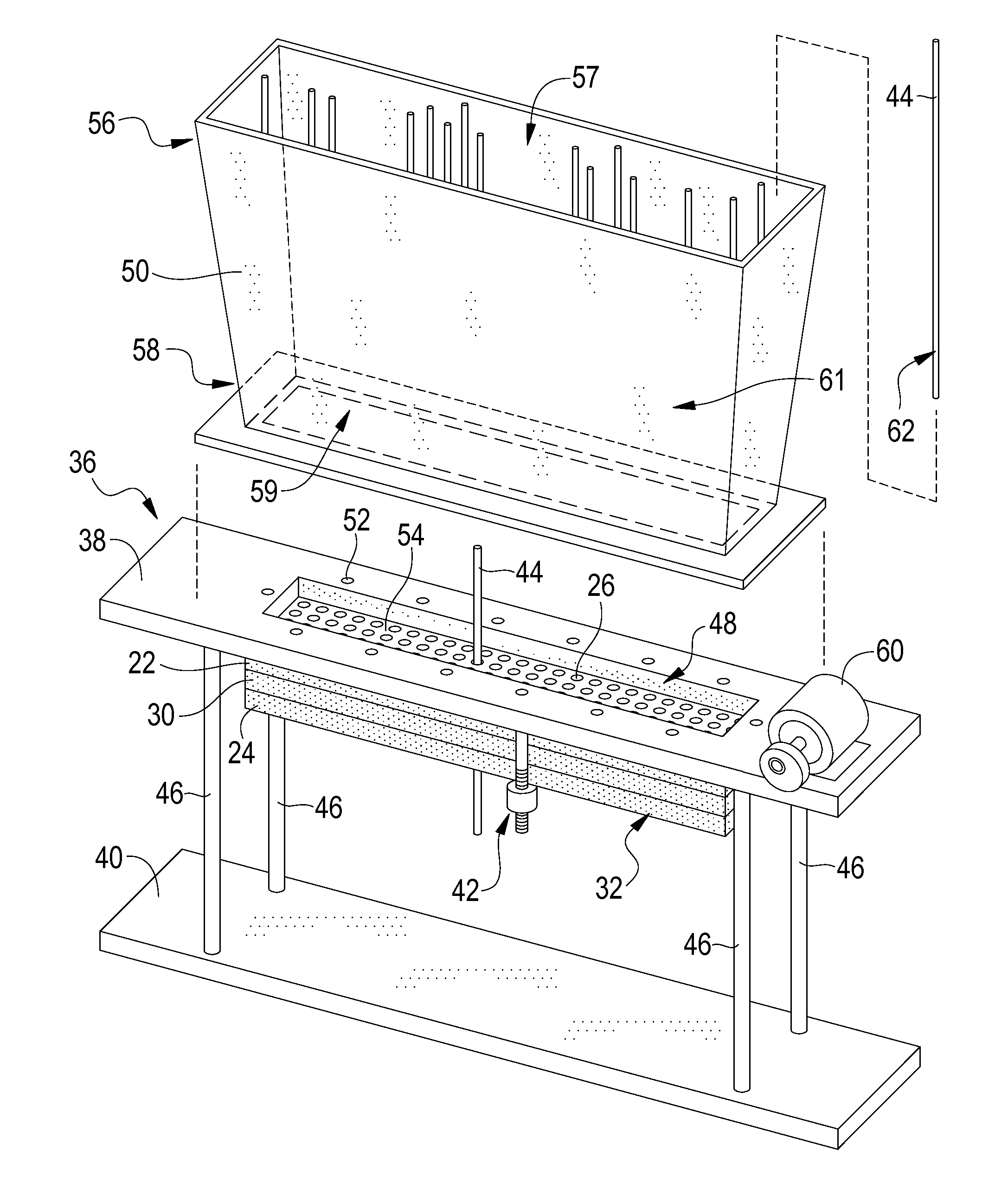
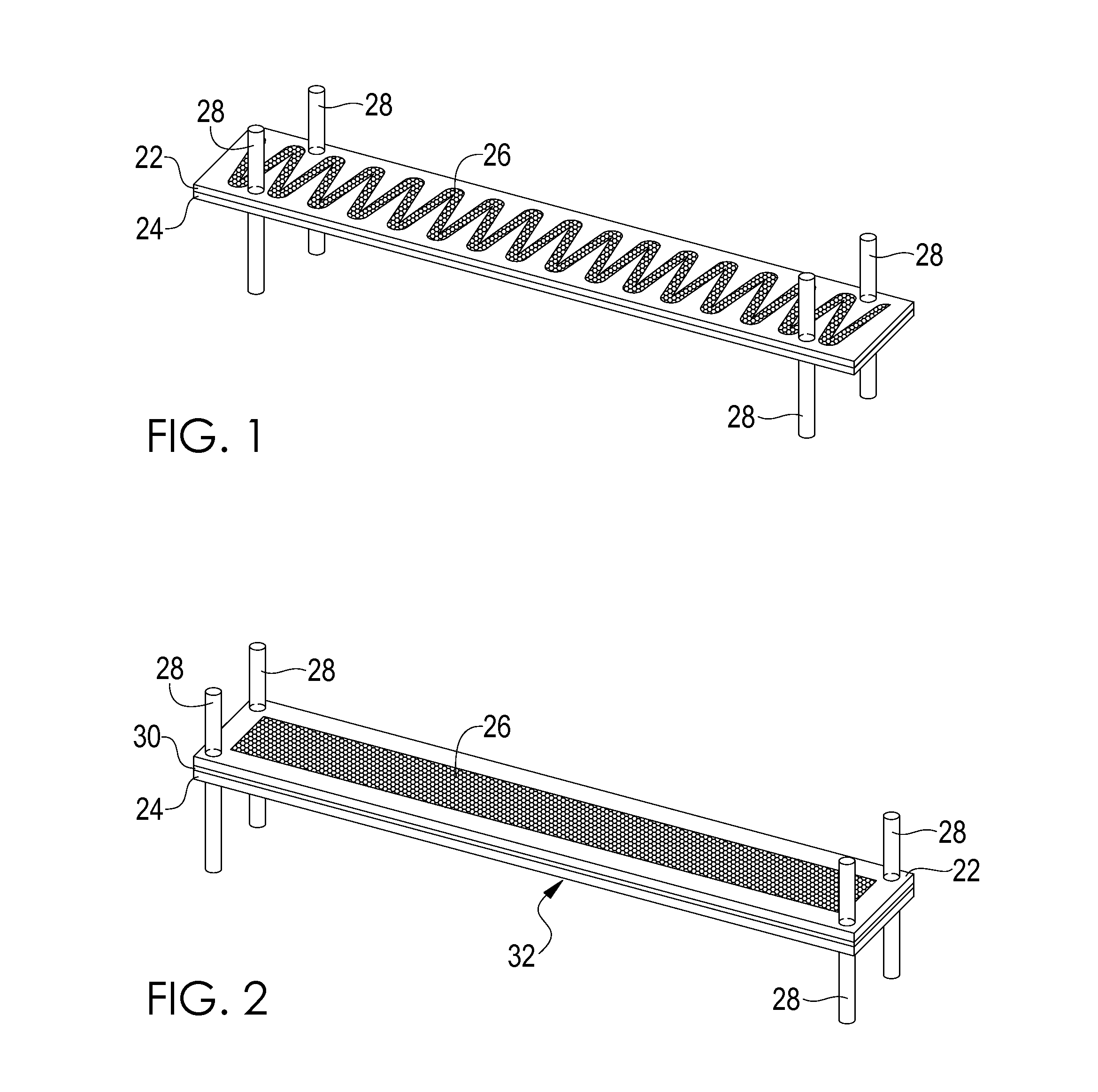
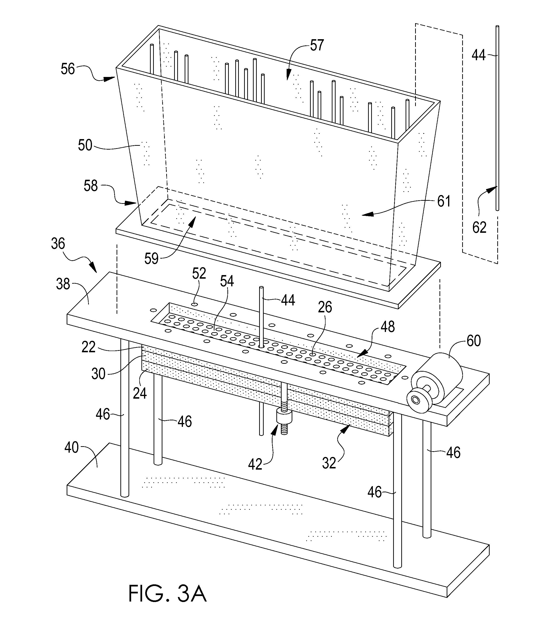
[0035]Turning now to the Figures, one embodiment of the present invention includes a method for manufacturing a heat exchanger component 20 as shown in FIG. 9. As shown in FIG. 1, in at least one embodiment, two end plates may be provided wherein the end plates provided are a first end ...


PUM

PropertyMeasurementUnit
Temperatureaaaaaaaaaa
Lengthaaaaaaaaaa
Adhesivityaaaaaaaaaa

Abstract

A method including disposing a first end plate adjacent to a second end plate, wherein the first end plate and second end plate each define a pattern of apertures. The first end plate is aligned with the second end plate such that the pattern of apertures in the first end plate is substantially aligned with the pattern of apertures in the second end plate. The method includes placing an end portion of each of a plurality of micro tubes in contact with the first end plate, the micro tubes being substantially vertically disposed and substantially perpendicular to a top surface of the first end plate, so as to place the micro tubes on the first end plate, and vibrating at least one of the micro tubes while the micro tubes are on the first end plate, thereby causing the micro tubes to insert into and through respective aligned apertures of the patterns of apertures in the first end plate and the second end plate. The method further includes separating the first end plate from the second end plate while the micro tubes extend therethrough, until the first end plate and the second end plate are disposed proximate to respective end portions of the micro tubes extending therethrough, and affixing each end portion of the micro tubes to a respective end plate, thereby forming a pathway in a micro tube heat exchanger component for the flow of an internal fluid to be heated or cooled by external flow of an external fluid.

Description

REFERENCE TO RELATED APPLICATIONS[0001]A claim is made to the benefit of the priorities of co-pending U.S. Patent Appl. No. 61 / 156,385, filed on Feb. 27, 2009, and co-pending U.S. Patent Appl. No. 61 / 224,002 filed on Jul. 8, 2009, the disclosures of which are incorporated herein by reference.[0002]The U.S. Government has provided support for the making of, and has certain rights in, this invention as provided for by the terms of Contract No. N68335-08-C-0127 awarded by the U.S. Department of the Navy.TECHNICAL FIELD[0003]This invention relates to a method for manufacturing heat exchangers, particularly heat exchangers comprising micro tubes.SUMMARY OF THE INVENTION[0004]Heat exchangers are used to transfer energy from one fluid to another. Heat exchangers are typically characterized by heat transfer rates between fluids and corresponding pressure drops of the fluid(s) across the heat exchanger. Examples of other performance metrics include volume, weight, cost, durability, and resis...

Claims


Application Information

Patent Timeline
IPC IPC(8): B29C65/72B32B37/12B32B37/02B23K35/02
CPCB21D53/02B21D53/08F28D1/05333F28D7/16F28F9/0131Y10T29/4935F28F9/18F28F2260/02F28F2275/04Y10T156/10F28F9/162
Inventor BECNEL, CHARLES J.MCLEAN, JEFFREY J.
Owner INT MEZZO TECH
Why Eureka
Try Eureka