Combustion inhibitor coating for gas generants

a technology of combustion inhibitors and gas generants, which is applied in the direction of explosives, pedestrian/occupant safety arrangements, vehicular safety arrangements, etc., can solve the problems of more complex and expensive dual stage inflators

Inactive Publication Date: 2011-02-03
AUTOLIV ASP INC
View PDF9 Cites 16 Cited by
  • Summary
  • Abstract
  • Description
  • Claims
  • Application Information

AI Technical Summary

Benefits of technology

In yet other aspects, methods of forming gas generants are provided. In certain aspects, a method of coating a gas generant comprises applying an aqueous mixture comprising a solubilized inorganic combustion inhibitor to at least a portion of a surface of a gas generant material comprising a fuel component and an oxidizer component. The aqueous mixture applied to the surface is dried to form a coating on at least a portion of the surface for inhibiting combustion.

Problems solved by technology

Unfortunately, dual stage inflators can be more complex and expensive.
In certain aspects, plastic coatings or other materials delivered in an organic solvent carrier to the gas generant may delay combustion; however undesirably contribute to undesirable gas effluents during combustion and airbag deployment.

Method used


Image

  • Combustion inhibitor coating for gas generants
  • Combustion inhibitor coating for gas generants
  • Combustion inhibitor coating for gas generants

Examples


example 1

Monoammonium phosphate in the amount of 25 grams is dissolved in 75 mL of water to form an aqueous mixture and placed inside a spray bottle. Approximately 50 grams of gas generant tablets having a diameter of about 0.25 inches (6.4 mm) and a thickness of about 0.080 inches (2 mm) are placed inside of a perforated stainless steel cylinder or drum of a rotating device. Standard tablets have an exemplary gas generant material comprising guanidine nitrate, basic copper nitrate, aluminum oxide, and silicon dioxide. The drum is placed horizontally on a rotating device that rotates the barrel around its longitudinal axis. The interior of the drum is equipped with baffles that continually move the gas generant tablets as the drum rotates. The walls of the drum have perforations that are smaller than the gas generant tablets but allow flow of a heated stream of air through the barrel as it rotates, facilitating rapid drying of the inhibitor solution on the surface of the tablets.

Coating is p...

example 2

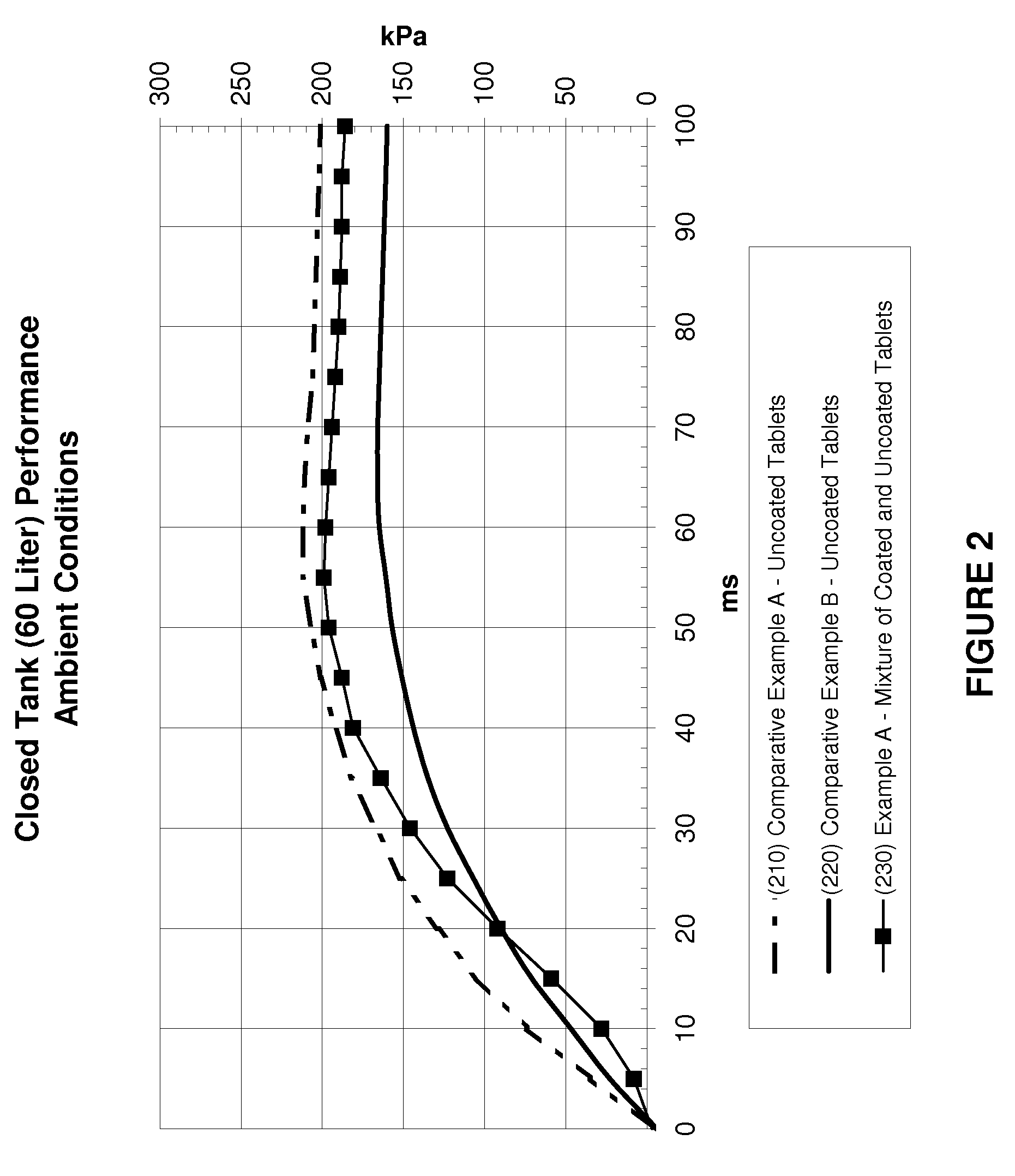
To further illustrate advantages of the present technology, gas generants having polymeric coatings and solvent applied coatings are prepared in accordance with the technique discussed in Example 1 and compared with a gas generant embodiment having a combustion inhibitor coating comprising ammonium phosphate as the inorganic combustion inhibitor. The Ro-Tap® sieve shaker device and mesh screen, as described above, is used to perform vibration tests to ascertain the relative strength of various polymeric coatings compared to the present inorganic combustion inhibitor coating. Five comparative examples of polymer igniter coatings are prepared and tested, where solid igniter particles are suspended in an organic solvent with a dissolved polymeric binder. The solvent solution is then sprayed onto the surface of gas generant tablets and subjected to the vibration test in the Ro-Tap® sieve shaker device. Results are provided in terms of weight loss experienced by the coated tablets follow...


PUM

PropertyMeasurementUnit
weight percentaaaaaaaaaa

Abstract

Methods of making and resultant compositions thereof, which include a gas generant having a coating including an inorganic combustion inhibitor. Such coated gas generants are useful in pyrotechnic compositions and ignition materials, and may be employed, for example, in inflatable restraint systems. The ratio of coated and uncoated gas generant bodies within an airbag inflator may be tailored to provide S-curve inflation performance. Spray application of aqueous mixture including the combustion inhibitor onto the gas generant body provides a rapid way to achieve a thin but robust coating.

Description

FIELDThe present disclosure generally relates to ignitable compositions, such as gas generant compositions used in inflatable restraint systems, and more particularly to combustion inhibitor coatings for gas generant compositions.INTRODUCTIONThe statements in this section provide background information related to the present disclosure and may not constitute prior art.Passive inflatable restraint systems are used in a variety of applications, such as motor vehicles. Some types of passive inflatable restraint systems minimize occupant injuries by using a pyrotechnic gas generant to inflate an airbag cushion (e.g., gas initiators and / or inflators) or to actuate a seatbelt tensioner (e.g., micro gas generators), for example. Automotive airbag inflator safety requirements and performance needs continually increase in order to further enhance passenger safety.In some applications, airbag inflators exhibiting a sigmoidal relationship of pressure versus time are desired. This sigmoidal per...

Claims


Application Information

Patent Timeline
Patent Type & Authority Applications(United States)
IPC IPC(8): B60R21/26C06D5/00B05D3/02
CPCB60R21/2644C06B45/12C06B21/0083
Inventor MENDENHALL, IVAN V.LUND, GARY K.HUSSEY, BRETT
Owner AUTOLIV ASP INC
Why Eureka
Try Eureka