
Glass laminate, display panel with support, method for producing glass laminate and method for manufacturing display panel with support

a technology of glass substrate and support, which is applied in the direction of electrical apparatus construction details, instruments, chemistry apparatus and processes, etc., can solve the problems of glass substrate not being processed in current production lines, glass substrate thinning becoming important problems, and fine scratches on the surface of glass substrate, etc., to suppress the occurrence of glass defects, suppress the generation of gas, and easily separate closely contacted thin glass substrate

Inactive Publication Date: 2011-02-03
ASAHI GLASS CO LTD
View PDF2 Cites 61 Cited by
  • Summary
  • Abstract
  • Description
  • Claims
  • Application Information

AI Technical Summary

Benefits of technology

[0028]The present invention is accomplished in consideration of the problems as mentioned above. That is, an object is to provide a glass laminate capable of suppressing the occurrence of glass defects induced by foreign matter such as air bubbles and dust entrained between the glass substrates, capable of being treated in a current production line without generating etch pits, and capable of easily separating the closely contacted thin glass substrate from the resin layer.
[0060]Also, it is possible to provide a glass laminate which suppresses the generation of a gas to an extremely minute amount at a thermal treatment under a high vacuum.
[0061]Moreover, according to a preferred embodiment, it is possible to provide a glass laminate wherein the resin layer between the thin glass substrate and the supporting glass substrate is hardly oxidized and is hardly deteriorated even when the thermal treatment temperature is relatively high (on the order of more than 400° C.).
[0031]Furthermore, an object is to provide a support attached-panel for a display device containing such a glass laminate. Also, an object is to provide a panel for a display device and a display device formed by using such a support attached-panel for a display device. Further, an object is to provide a method for producing the glass laminate or a method for producing the support attached-panel for a display device.

Problems solved by technology

In the field of liquid crystal display devices (LCD) and organic EL display devices (OLED), particularly mobile-type display devices such as mobiles and cellular phones, weight saving and thinning of the display devices become important problems.
Therefore, there arises a problem that the glass substrate cannot be processed in current production lines.
Moreover, when the glass substrate is thinned by performing the etching treatment or the like after the formation of a member for a display device on a surface of the glass substrate, there arises a problem that fine scratches formed on the surface of the glass substrate in the process of forming the member for a display device on the glass substrate become marked, i.e., a problem of occurrence of etch pits.

Method used


Image

  • Glass laminate, display panel with support, method for producing glass laminate and method for manufacturing display panel with support
  • Glass laminate, display panel with support, method for producing glass laminate and method for manufacturing display panel with support
  • Glass laminate, display panel with support, method for producing glass laminate and method for manufacturing display panel with support

Examples


example 1

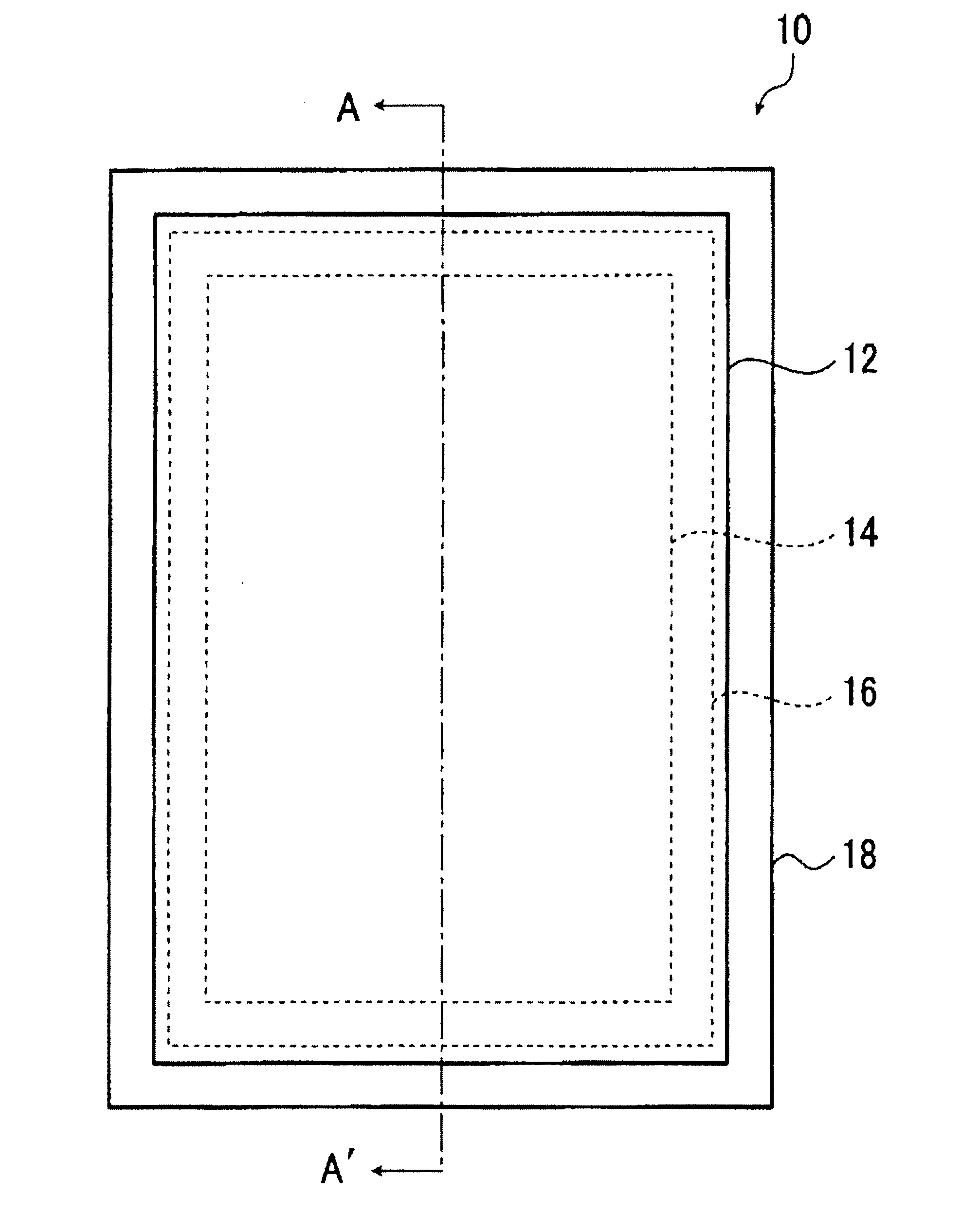
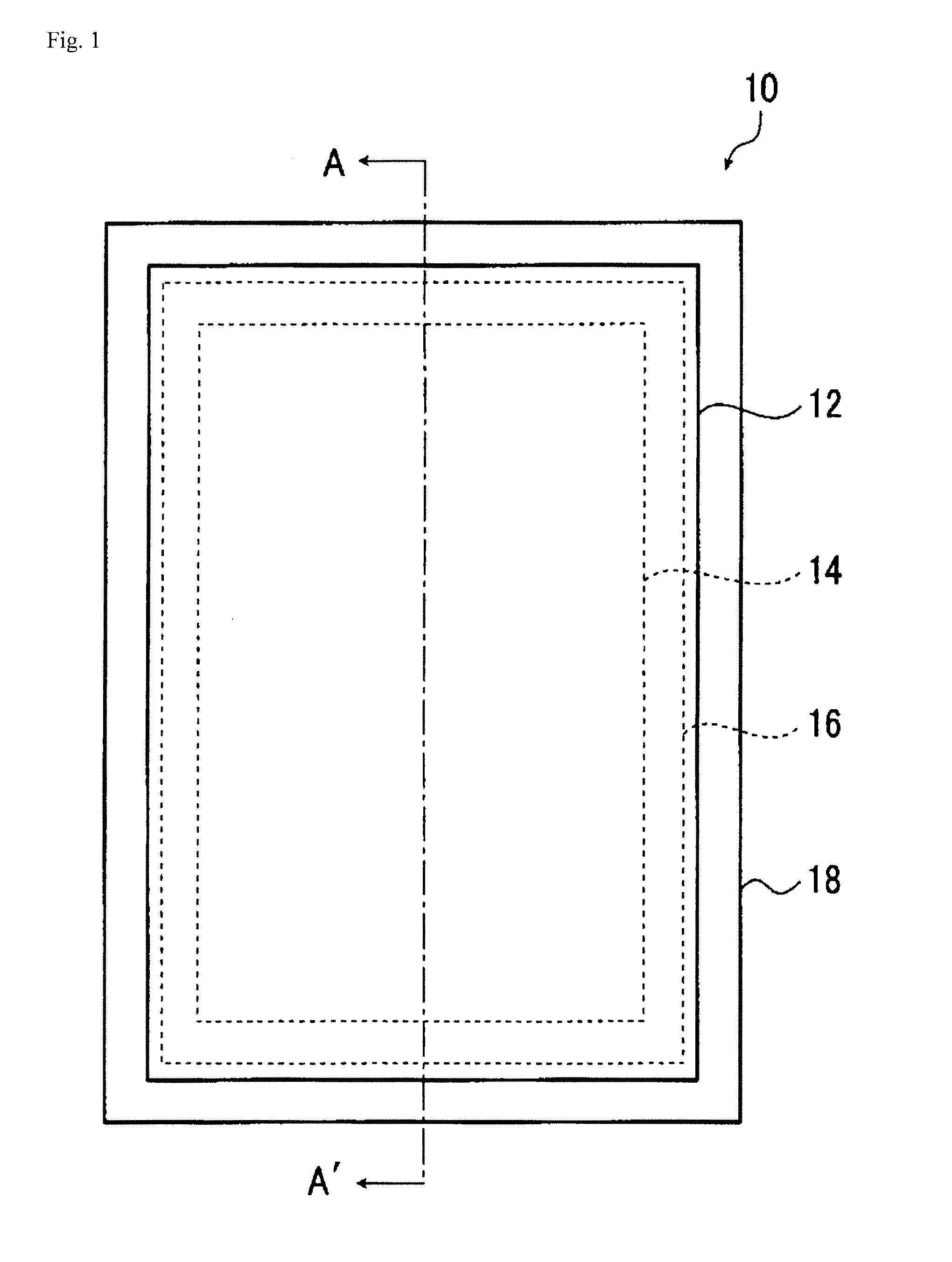
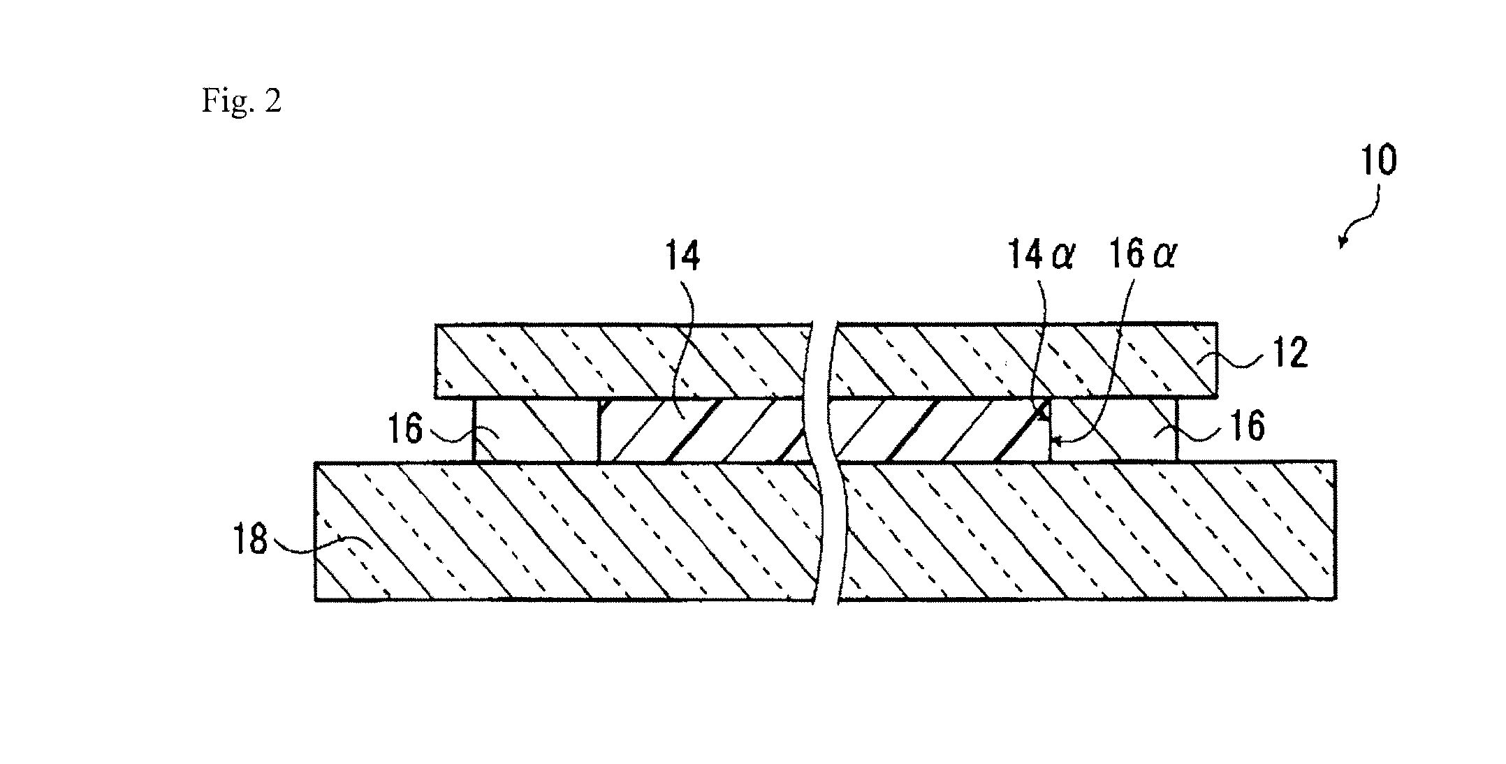
[0238]About the same glass laminate as the glass laminate according to the embodiment 1 described with reference to the aforementioned FIG. 1 and FIG. 2 was produced by the following method. A difference from the embodiment 1 lies only in sizes of the thin glass substrate and the supporting glass substrate. In the glass laminate according to the embodiment 1, the thin glass substrate 12 is smaller in main surface area than the supporting glass substrate 18 but, in the glass laminate to be produced in Example 1, the sizes of both glass substrates are the same.

[0239]First, a supporting glass substrate having a length of 720 mm, a width of 600 mm, a thickness of 0.4 mm, and a linear expansion coefficient of 38×10−7 / ° C. (manufactured by Asahi Glass Co., Ltd., AN100) was subjected to cleaning with pure water and UV cleaning to clean the surface.

[0240]Next, a mixture of 100 parts by mass of a non-solvent addition reaction-type silicone for release paper (manufactured by Shin-Etsu Silicon...

example 2

[0251]Two sheets of a glass laminate were produced by performing the same operations as in Example 1 except that a thermoplastic polyimide resin (manufactured by Mitsui Chemicals Inc., AURUM PLC 450C (5% mass loss temperature upon heating=570° C.)) was used and, after melting, the outer frame layer was formed by an extrusion dispense method. Then, a “glass laminate B-1” not subjected to the heating treatment and a “glass laminate B-2” subjected to the heating treatment were obtained in a similar manner to the case of Example 1. In this regard, the glass laminate B was separately heated from room temperature to 450° C. under a high vacuum (1.0×10⁻⁵ Pa) but no gas was generated from the glass laminate B. In the glass laminate B-1 and the glass laminate B-2 obtained, the thin glass substrate had been in close contact with the silicone resin layer without having air bubbles and was also satisfactory in smoothness without any convex defect.

[0252]Moreover, when the above peeling test 1 wa...

example 3

[0253]Example 3 is the same as Example 1 except that a supporting glass substrate, a resin layer, an outer frame layer, and a thin glass substrate different in kind, size, thickness, etc. were used.

[0254]As the supporting glass substrate, a glass substrate having a length of 720 mm, a width of 600 mm, a thickness of 0.6 mm, and a linear expansion coefficient of 38×10−7 / ° C. (manufactured by Asahi Glass Co., Ltd., AN100) was used.

[0255]Moreover, as a resin for forming the resin layer, a linear polyorganosiloxane having a vinyl group in both terminal ends (manufactured by Arakawa Chemical Industries, Ltd., trade name “8500”) and a methyl hydrogen polysiloxane having a hydrosilyl group in the molecule (manufactured by Arakawa Chemical Industries, Ltd., trade name “12031”) were used. Then, they were mixed with a platinum-based catalyst (manufactured by Arakawa Chemical Industries, Ltd., trade name “CAT12070”) to prepare a mixture, which was applied in a size of a length of 700 mm and a ...


PUM

PropertyMeasurementUnit
mass loss temperatureaaaaaaaaaa
widthaaaaaaaaaa
temperatureaaaaaaaaaa

Abstract

Disclosed is a glass laminate comprising a thin glass substrate having a first main surface and a second main surface, a supporting glass substrate having a first main surface and a second main surface, and a resin layer and an outer frame layer arranged between the thin glass substrate and the supporting glass substrate. The resin layer is fixed to the first main surface of the supporting glass substrate and is in close contact with the first main surface of the thin glass substrate, while having easy releasability from the first main surface of the thin glass substrate. The outer frame layer surrounds the resin layer on the first main surface of the supporting glass substrate so that the outside air does not come into contact with the resin layer.

Description

TECHNICAL FIELD[0001]The present invention relates to: a glass laminate containing glass substrates for use in liquid display devices, organic EL display devices and the like; a support attached-panel for a display device containing the same; a panel for a display device formed using the same; and a display containing the same. The present invention relates to a method for producing the glass laminate and a method for producing the panel for a display device.BACKGROUND ART[0002]In the field of liquid crystal display devices (LCD) and organic EL display devices (OLED), particularly mobile-type display devices such as mobiles and cellular phones, weight saving and thinning of the display devices become important problems.[0003]In order to cope with the problems, it is desired to further reduce the thickness of a glass substrate for use in the display devices. As a method for reducing the thickness, in general, there is performed a method of subjecting the glass substrate to an etching...

Claims


Application Information

Patent Timeline
Patent Type & Authority Applications(United States)
IPC IPC(8): H05K7/00B32B37/12B32B3/02
CPCB32B7/06G02F2001/133302B32B17/10G02F1/133302
Inventor KONDO, SATOSHIEBATA, KENICHI
Owner ASAHI GLASS CO LTD
Learn More