Free flow hydro-powered hydraulic ram

a hydro-powered hydraulic ram and free flow technology, applied in the direction of fluid couplings, electric generator control, couplings, etc., can solve the problems of large energy consumption, large energy consumption, and inability to meet the needs of hydro-powered hydraulic rams,

Active Publication Date: 2011-02-24
FRYE CLARENCE EDWARD
View PDF20 Cites 17 Cited by
  • Summary
  • Abstract
  • Description
  • Claims
  • Application Information

AI Technical Summary

Benefits of technology

[0114]As shown in FIG. 6D, the jet pump reduces the pressure behind the nozzle C and causes water t

Problems solved by technology

In the present circumstances, the common source of energy is by fossil-based fuels, which are not environmentally friendly and are finite in quantity.
This requires a large amount of energy.
Some wou

Method used


Image

  • Free flow hydro-powered hydraulic ram
  • Free flow hydro-powered hydraulic ram
  • Free flow hydro-powered hydraulic ram

Examples


first embodiment

Overview of Invention

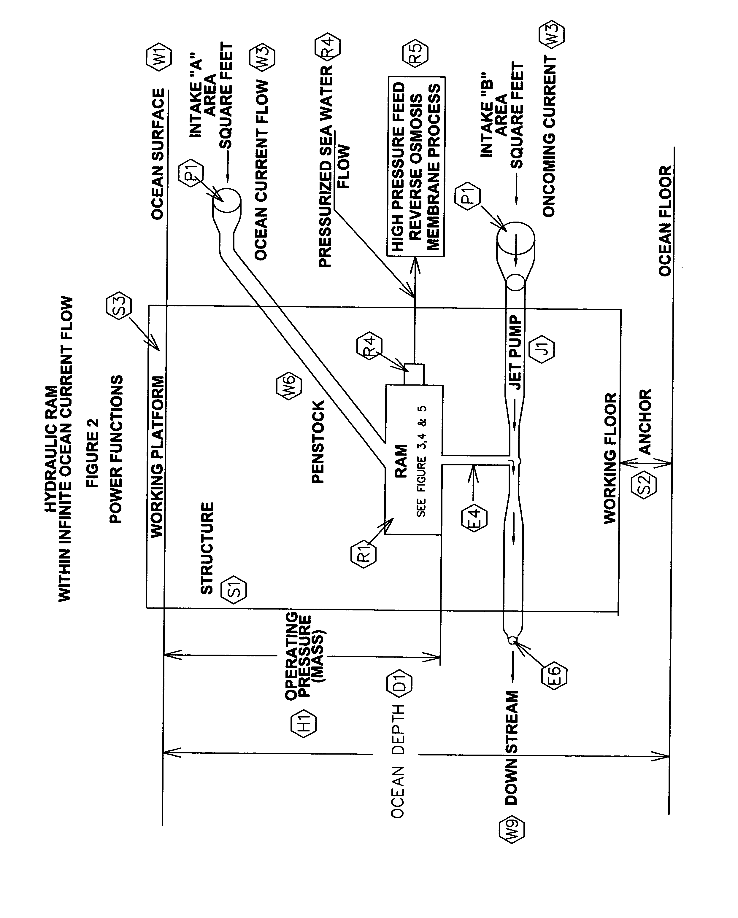
[0117]This invention is in all respects a linear hydraulic motor which can perform all four-cycle engine functions simultaneously. The preferred embodiment, when placed and operated at a depth, within a body of water, is in fact, an infinite molecular power source.

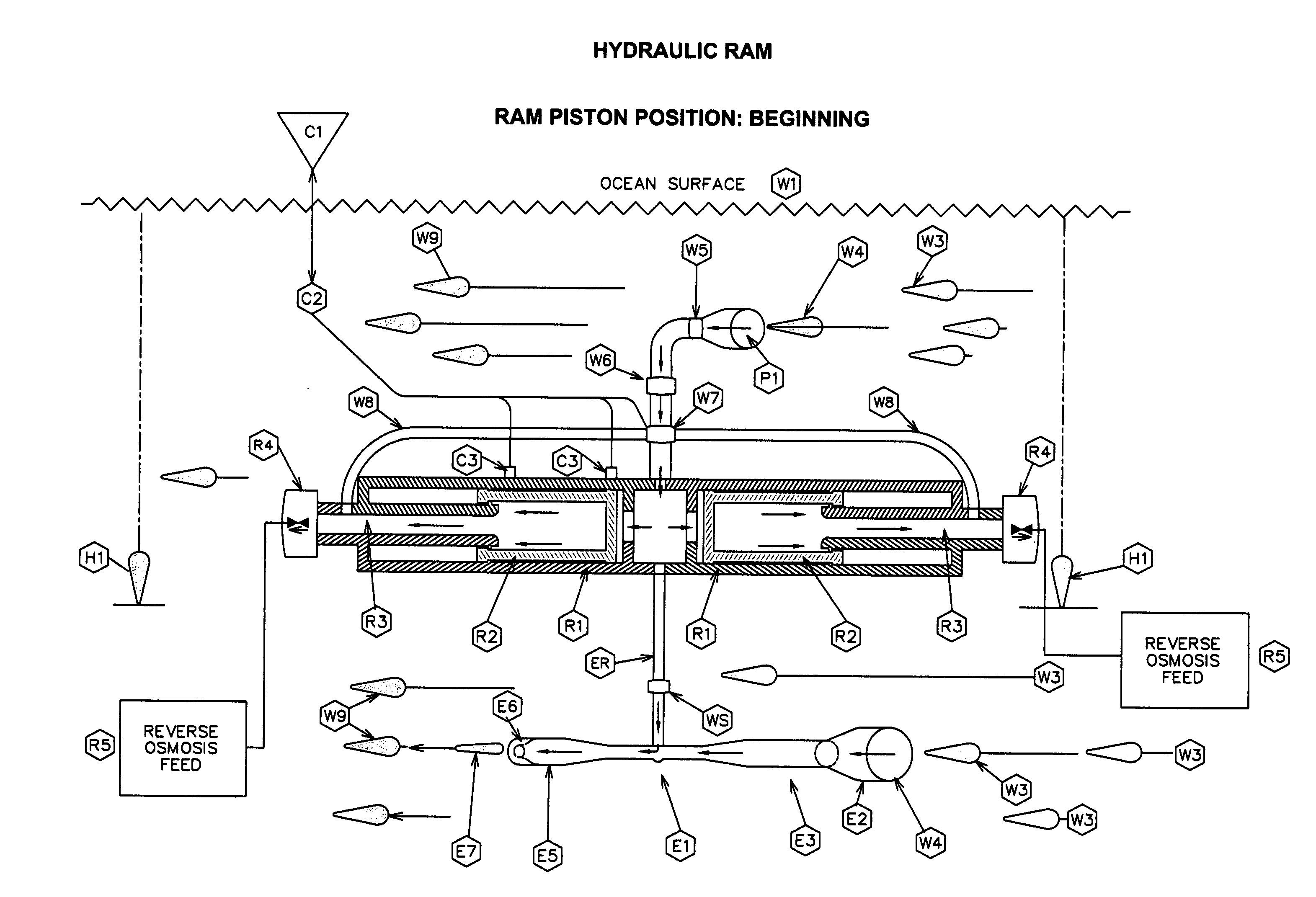
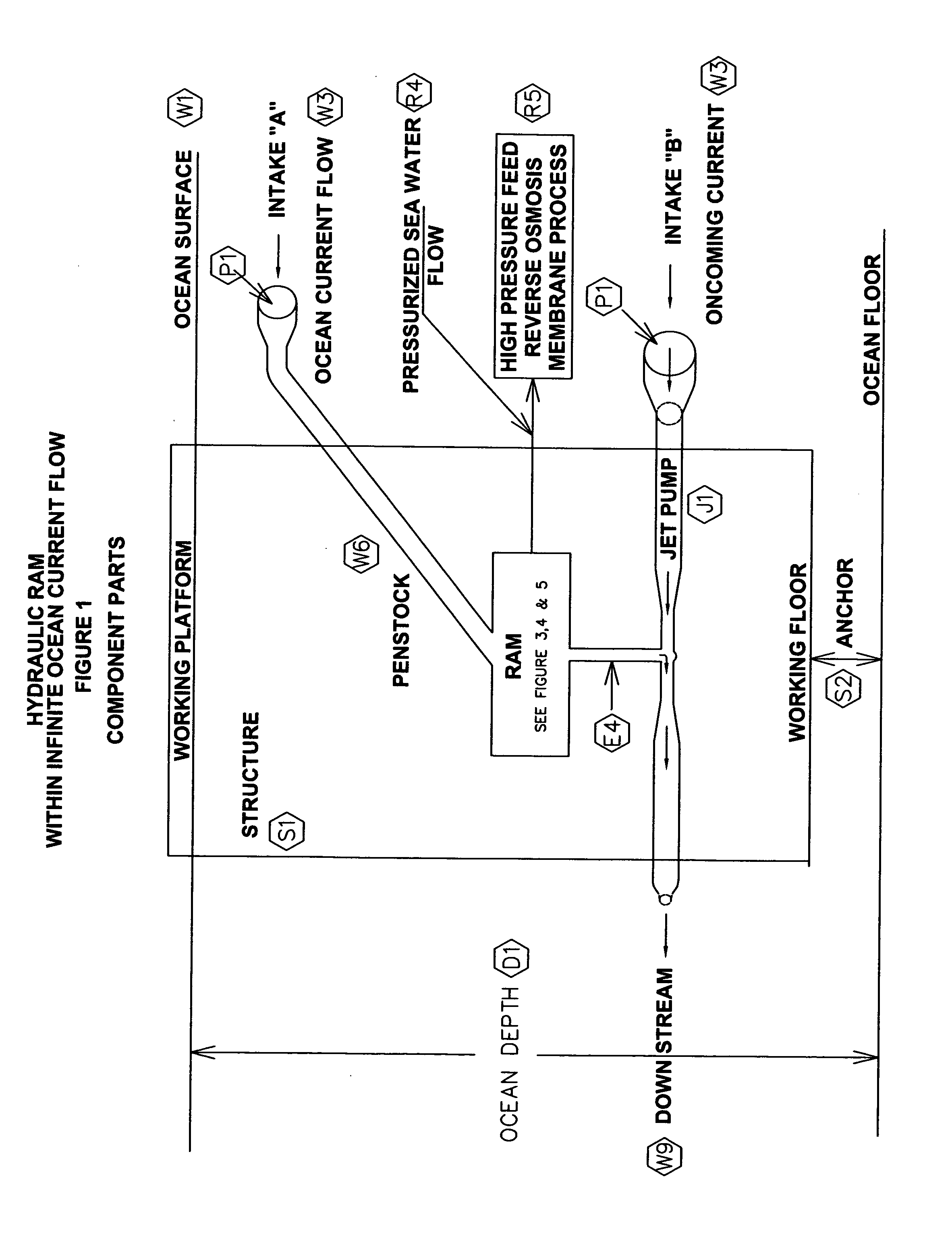
[0118]To begin, the hydro-power hydraulic ram (FIG. 1) is positioned in a body of flowing water (mass), at a depth and positioned by structure, attachment, or tether. The system's shrouded intake ports must be oriented so as to be directly facing the oncoming stream of flowing water. The exit or discharge point faces downstream.

[0119]The water flow passes thru the shrouded input port and flows through the inline replaceable filter and fills the conduit until it applies its restrained, force against the (S1) closed solenoid switched valve which control entry or denial into the ports of the three (3) chambers. One (C1) port opens into the central chamber of the ram cylinder. This is the power stroke cham...


PUM


Abstract

This water powered hydraulic ram, when housed in a supporting water-tight structure deep within a moving body of water, functions essentially as a four cycle engine with water as it prime mover. It is a linear motor, just as if it were powered by ordinary fossil-based fuels. This invention harnesses the force of moving water and the pressure of water at a depth and becomes a prime mover whose output is hydro-power. When water is confined in a solid body and its force is applied to the surface of a piston, that force is transmitted equally, in all directions throughout the fluid or gas in the form of pressure. It is a machine. This characteristic observes “Pascal's Law”. The component parts of this linear motor are a hydraulic ram cylinder, sliding ram pistons, a Venturi/Eductor jet pump, electronic piston positioning sensors, solenoid controlled valves and process program software. It is positioned to face an oncoming, irresistible downstream water force. It may be either singular or in plurality as an array, this being a site adaptation design issue. Its purpose is to transform the limitless energy from moving water. It is an integration of existing technology of various fields. It is applicable to any comparable moving fluid source, particularly water. The coastal Gulf Stream and other ocean currents provide ideal environments as infinite sources of renewable energy. Being operative in an infinite body of seawater, the highest priority application should be to apply pressure to seawater and pass it through a reverse osmosis membrane to remove the salt, The product would be unlimited quantities of potable, fresh drinking water.

Description

CROSS REFERENCE TO RELATED PATENTS[0001]U.S. Pat. No. 873, 435 Dec. 10, 1907 Fall Increaser[0002]U.S. Pat. No. 7,240,631 B1 10 Jul. 2007 Loop Ballast Exchange System for Marine Vessels[0003]U.S. Pat. No. 6,766,754 27 Jul. 27, 2004. Ballast Exchange System For Marine VesselsCROSS REFERENCE TO RELATED APPLICATIONS[0004]U.S. Pat. No. 0,320,459 A1 31 Dec. 2009 HYDRO-ACTUATED ENGINE[0005]Ser. No. 12 / 658,761 12 Feb. 2010 FREE FLOW HYDRO-POWERED TURBINE SYSTEMCROSS REFERENCE TO RELATED PROVISIONAL PATENTS[0006]No. 61 / 272,343 15 Sep. 2009 FREE FLOW HYDRO-POWERED RAMFEDERALLY SPONSORED RESEARCH RELATED APPLICATIONS[0007]Not ApplicableCLASSIFICATION CODESCurrent U.S. Class: 60 / 398Current International Class: F03B 13 / 00Field of Search: 60 / 398, 290 / 42, 43, 53, 54 416 / 64, 79, 83[0008]Paris Convention Number of this Invention: US61 / 213,247BACKGROUND[0009]1. Field of Invention[0010]This application relates to a structure which encompasses a free-flow hydro-powered hydraulic ram submerged deep in a...

Claims


Application Information

Patent Timeline
IPC IPC(8): F03B13/10
CPCF03B17/00F05B2220/62Y02E10/20F05B2260/601F05B2240/97
Inventor FRYE, CLARENCE EDWARD
Owner FRYE CLARENCE EDWARD
Why Eureka
Try Eureka