
Piezoelectric actuator, method for manufacturing piezoelectric actuator, liquid-ejecting head, and liquid-ejecting apparatus

a piezoelectric actuator and actuator technology, applied in piezoelectric/electrostrictive transducers, generators/motors, device material selection, etc., can solve problems such as difficulty in stopping etching

Inactive Publication Date: 2011-02-24
SEIKO EPSON CORP
View PDF1 Cites 12 Cited by
  • Summary
  • Abstract
  • Description
  • Claims
  • Application Information

AI Technical Summary

Benefits of technology

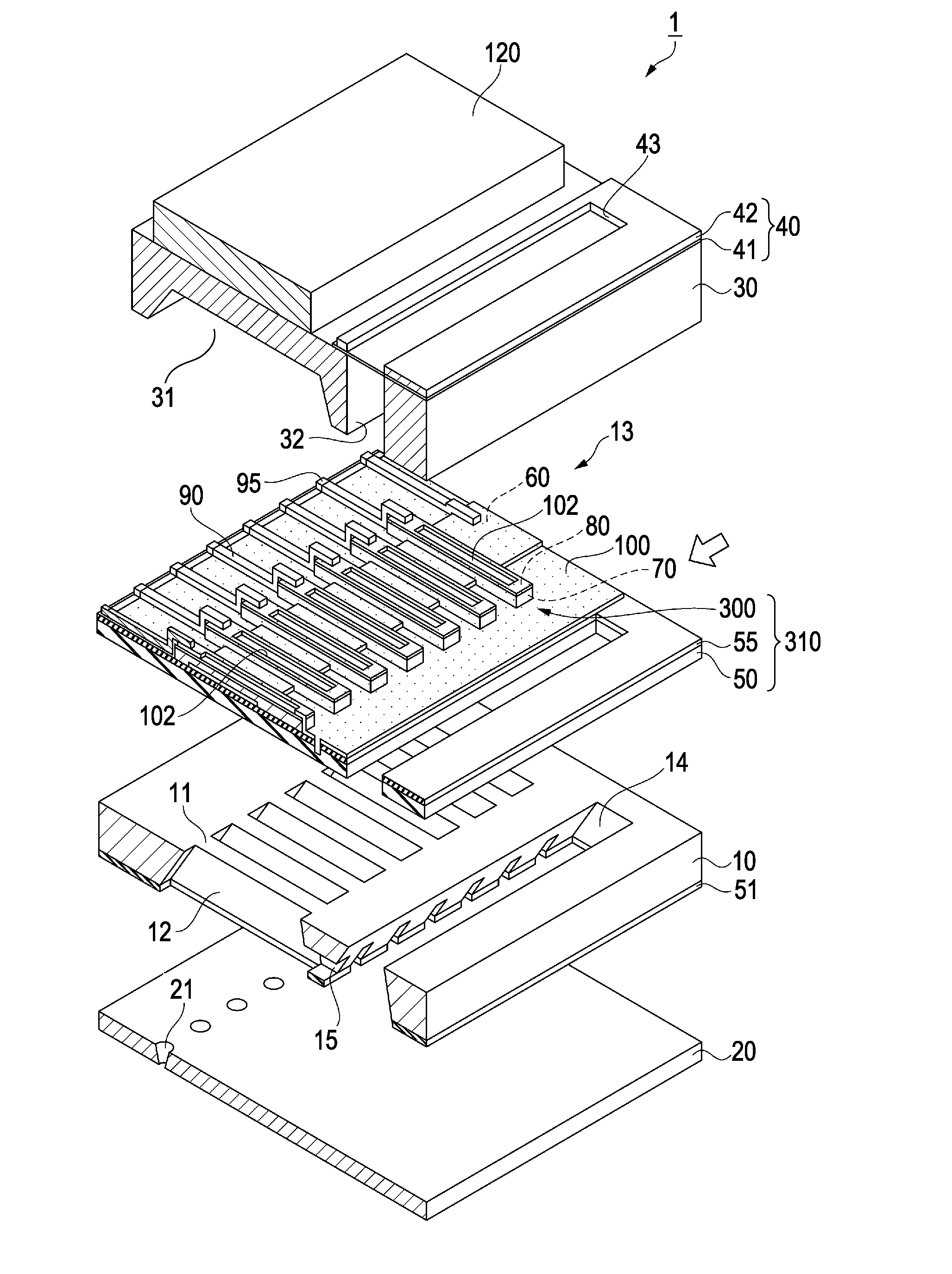
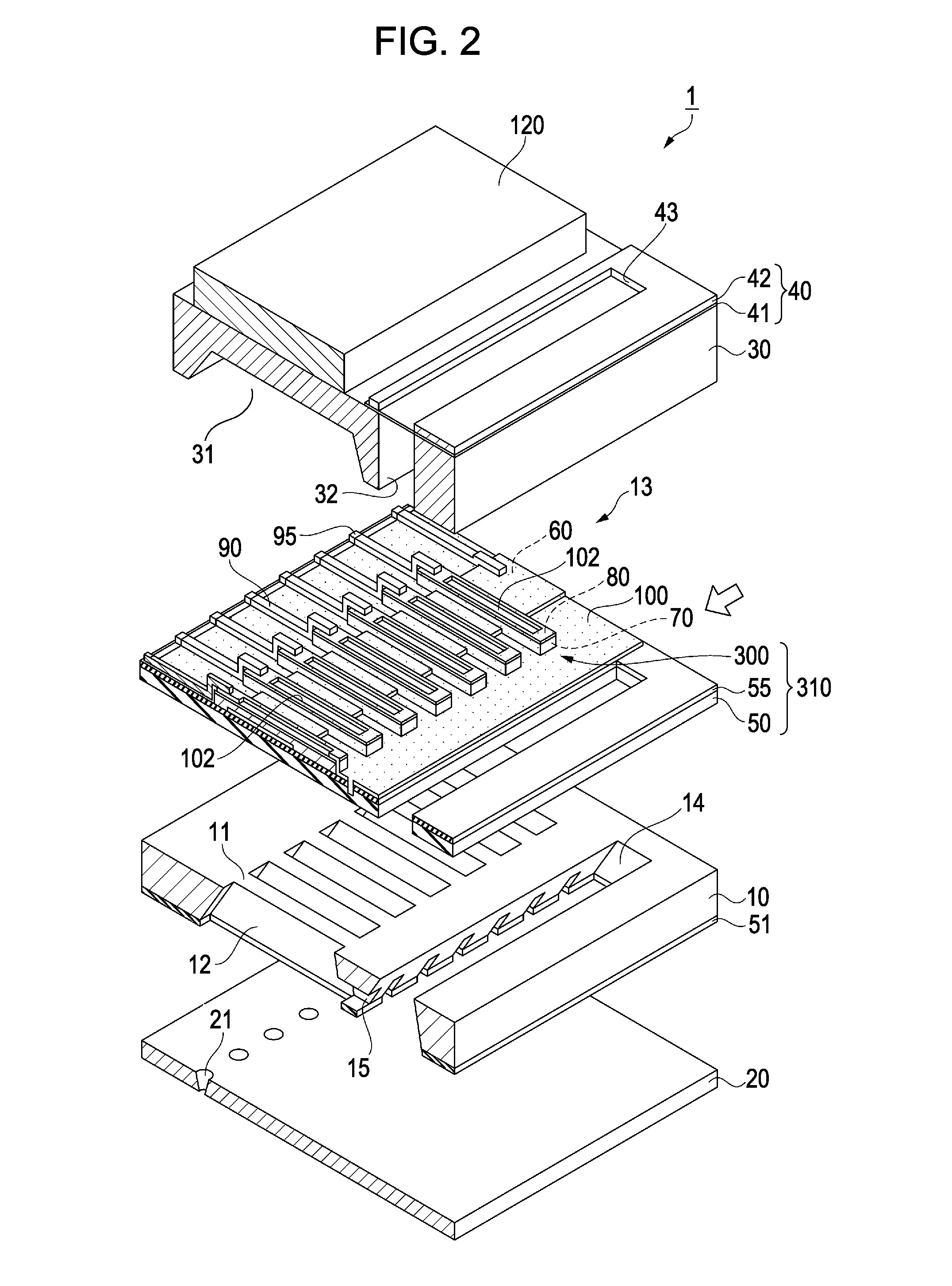
In the piezoelectric actuator, the second sputtering rate of the second upper sub-electrode is less than the first sputtering rate of the first upper sub-electrode; hence, the second upper sub-electrode is more resistant to sputtering when the portion of the protective film that is disposed on the second upper sub-electrode is removed by sputtering as compared to the case where the upper electrode includes the first upper sub-electrode only and therefore a difference in thickness of the second upper sub-electrodes can be reduced. Therefore, the inhibitory effect of the upper electrode on the deformation of the piezoelectric body can be reduced. This allows the piezoelectric actuator to have small differences in vibrational properties.
In the method, the sputtering uses argon and the first and second sputtering rates are those determined with argon. Argon is an inert gas. Therefore, it hardly occurs that argon combines with the second upper sub-electrode to adversely affect properties of the second upper sub-electrode. Argon has an atomic weight greater than that of nitrogen or another gas and therefore has a high sputtering rate. Therefore, the use of argon is effective in reducing the time taken to partly remove the protective film and the piezoelectric actuator can be manufactured by the method at low cost.

Problems solved by technology

Therefore, it is difficult to stop etching at the boundary between the insulating protective film and an electrode of each piezoelectric element; hence, the electrode is etched and the thickness of the electrode varies depending on portions of the wafer.

Method used


Image

  • Piezoelectric actuator, method for manufacturing piezoelectric actuator, liquid-ejecting head, and liquid-ejecting apparatus
  • Piezoelectric actuator, method for manufacturing piezoelectric actuator, liquid-ejecting head, and liquid-ejecting apparatus
  • Piezoelectric actuator, method for manufacturing piezoelectric actuator, liquid-ejecting head, and liquid-ejecting apparatus

Examples


Embodiment Construction

Embodiments of the present invention will now be described in detail with reference to the accompanying drawings.

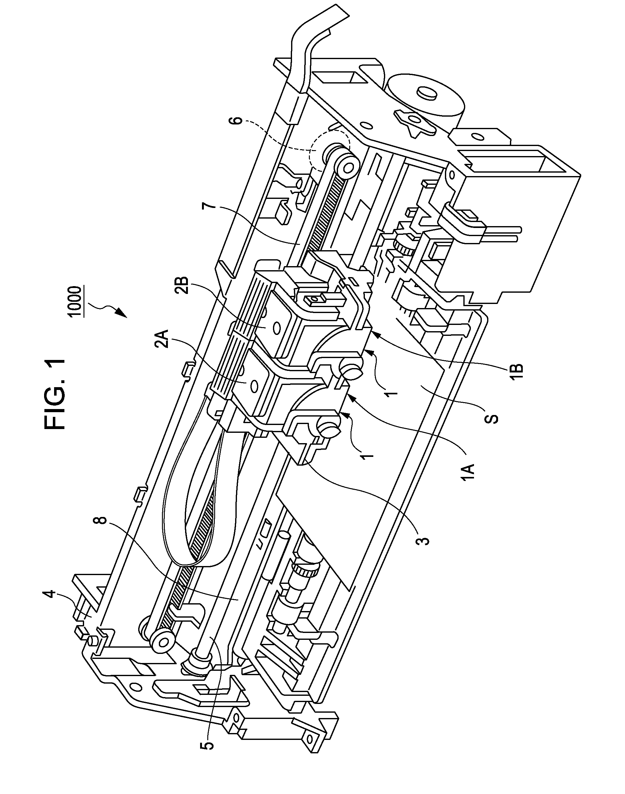
FIG. 1 is a schematic view of an ink jet recording apparatus 1000 according to an embodiment of the present invention. The ink jet recording apparatus 1000 corresponds to a liquid-ejecting apparatus and is a type of equipment that ejects ink which is a liquid toward a recording sheet S which is a recording medium to perform recording.

With reference to FIG. 1, the ink jet recording apparatus 1000 includes a first recording head unit 1A and second recording head unit 1B each including an ink jet recording head 1 which corresponds to a liquid-ejecting head. The first recording head unit 1A and the second recording head unit 1B include a first cartridge 2A and a second cartridge 2B, respectively. The first and second cartridges 2A and 2B are detachable and form an ink supply member.

The ink jet recording heads 1 are located on the sides of the first and second recording head u...


PUM

PropertyMeasurementUnit
thicknessaaaaaaaaaa
thicknessaaaaaaaaaa
thicknessaaaaaaaaaa

Abstract

A piezoelectric actuator includes a substrate; a diaphragm overlying the substrate; a lower electrode overlying the diaphragm; a piezoelectric body overlying the lower electrode; an upper electrode that includes a first upper sub-electrode which overlies the piezoelectric body and which has a first sputtering rate and also includes a second upper sub-electrode which overlies the first upper sub-electrode, which has a second sputtering rate less than the first sputtering rate, and which is the uppermost layer; and a protective film extending over side surfaces of the piezoelectric body and the second upper sub-electrode, a portion of the protective film that overlies the second upper sub-electrode being removed by sputtering.

Description

This application claims a priority to Japanese Patent Application No. 2009-188942 filed on Aug. 18, 2009 which is hereby expressly incorporated by reference herein in its entirety.BACKGROUND1. Technical FieldThe present invention relates to a piezoelectric actuator, a method for manufacturing the piezoelectric actuator, a liquid-ejecting head including the piezoelectric actuator, and a liquid-ejecting apparatus including the liquid-ejecting head.2. Related ArtPiezoelectric bodies including crystals of lead zirconate titanate (PZT) have spontaneous polarization, a high dielectric constant, electro-optic effects, piezoelectricity, and pyroelectricity and therefore are applied to various devices such as piezoelectric elements. The piezoelectric elements each include a pair of electrodes and are deformed by applying a voltage between the electrodes.Piezoelectric actuators make use of the fact that piezoelectric elements are deformed by the application of voltage. The piezoelectric actua...

Claims


Application Information

Patent Timeline
Patent Type & Authority Applications(United States)
IPC IPC(8): B41J2/045H01L41/053H01L41/22B05C5/00B41J2/055B41J2/135B41J2/14B41J2/16H01L41/09H01L41/18H01L41/187H01L41/23H01L41/29
CPCB41J2/055B41J2/14233B41J2/161B41J2/1623B41J2/1628B41J2/1629Y10T29/42B41J2/1642B41J2/1646B41J2002/14241B41J2002/14419H01L41/0533H01L41/314B41J2/1631H10N30/883H10N30/074
Inventor UMEDA, KATSUMI
Owner SEIKO EPSON CORP
Learn More