Wavelength converting device, laser, and method to stabilize the wavelength conversion efficiency

a wavelength conversion and wavelength technology, applied in the field of wavelength conversion devices, can solve the problems of destructive interference, temperature sensitivity of non-linear optical materials, clear limitation, and considerable decrease in conversion efficiency, and achieve the effect of maximizing the conversion efficiency and stabilizing the conversion efficiency of the wavelength conversion devi

Inactive Publication Date: 2011-02-24
KONINKLIJKE PHILIPS ELECTRONICS NV
View PDF6 Cites 16 Cited by
  • Summary
  • Abstract
  • Description
  • Claims
  • Application Information

AI Technical Summary

Benefits of technology

[0014]According to a third aspect, the invention provides a method to stabilize the conversion efficiency of a wavelength converting device comprising a non-linear optical crystal having periodically poled regions with alternating polarity, the method comprising the steps: (i) providing the period of the poled regions along an axis (X) of the device to vary in a direction (Y) perpendicular to the axis, and (ii) adjusting the position of the wavelength converting device along the direction (Y) perpendicular to the axis (X).
[0015]In an embodiment, the method further comprises the steps: (iii) assembling the wavelength converting device on a mount, and (iv) arranging the mount to have a calibrated thermal expansion allowing for maximization of the conversion efficiency through automatic compensation of temperature variations of the wavelength converting device by displacing it along the direction (Y).

Problems solved by technology

Due to the different speed a phase shift of π between the generated light and the fundamental wave exist at a so called coherence length Lc=λ / 4*(n3−n1), causing a destructive interference.
The temperature sensitivity of non-linear optical materials, however, forms a clear limitation of the solution described in U.S. Pat. No. 5,787,102.
This results in a considerable decrease in conversion efficiency.
This solution shows limited effectiveness and / or is difficult to implement for small size solid-state semiconductor lasers.

Method used


Image

  • Wavelength converting device, laser, and method to stabilize the wavelength conversion efficiency
  • Wavelength converting device, laser, and method to stabilize the wavelength conversion efficiency
  • Wavelength converting device, laser, and method to stabilize the wavelength conversion efficiency

Examples


Embodiment Construction

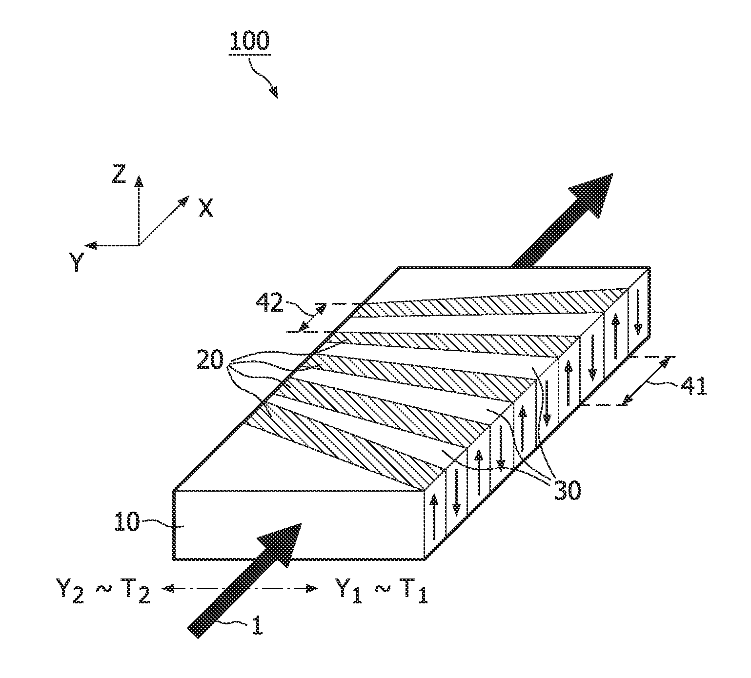
[0020]Second order nonlinear effects are usually relatively weak, yet it is possible to use them to generate frequency conversion processes at power levels suitable for practical applications. In sum and difference frequency mixing (SFM, DFM), two input photons, that travel through a nonlinear medium, are added or subtracted into one photon of higher or lower energy: ω3=ω1±ω2. When ω1=ω2=ω then ω3=2ω, the nonlinear susceptibility gives rise to second harmonic generation (SHG). Other types of nonlinear processes, down-conversion or optical parametric generation (OPG), start with one input photon and result in two photons of lower energies. The two generated wavelengths are referred to as signal and idler, of which the signal is the shortest one. When a cavity is used to enhance the efficiency by resonating one or both of the generated fields, the device is called an optical parametric oscillator (OPO).

[0021]In three-wave nonlinear processes, maximum output power levels are obtained w...


PUM

PropertyMeasurementUnit
thermal expansionaaaaaaaaaa
temperatureaaaaaaaaaa
lengthaaaaaaaaaa

Abstract

Proposed is a wavelength converting device (100) comprising a non-linear optical crystal (10) having periodically poled regions (20,30) with alternating polarity. The device (100) is characterized in that the period (41,42) of the poled regions along an axis (X) of the device vary in a direction (Y) perpendicular to the axis. The invention is based on the insight that a poling period corresponds to a given temperature. Thus, providing different poling periods along a direction in the wavelength converting device advantageously allows correlating the position of the device along that direction with a temperature.

Description

FIELD OF THE INVENTION[0001]The invention relates to a wavelength converting device comprising a non-linear optical crystal having periodically poled regions with alternating polarity. Furthermore, the invention relates to a laser comprising such a wavelength converting device. Moreover, the invention relates to a method to stabilize the conversion efficiency of such devices.BACKGROUND OF THE INVENTION[0002]An embodiment of a wavelength converting device and a laser of the kind set forth are known from U.S. Pat. No. 5,787,102. That document discloses a non-linear optical device applying a periodically poled lithium niobate (PPLN) crystal having regions with an alternating polarity, i.e. inverting the sign of the non-linear optical coefficient. Dispersion in non linear optical materials means that the refractive index n1 seen by the fundamental wave differs from the refractive index n3 seen by second harmonic generated light. As a result, the fundamental wave (with wavelength λ) trav...

Claims


Application Information

Patent Timeline
Patent Type & Authority Applications(United States)
IPC IPC(8): G02F1/37
CPCG02F2001/3546G02F1/3775G02F1/3546
Inventor HIKMET, RIFAT ATAA MUSTAFA
Owner KONINKLIJKE PHILIPS ELECTRONICS NV
Why Eureka
Try Eureka