Supporting unit for microfluid system

a technology of supporting unit and microfluid, which is applied in the direction of laboratory glassware, instruments, chemical/physical/physicochemical processes, etc., can solve the problems of increasing the number of channel layers, complicated production process, and difficult to produce such a system in commercial scale, so as to reduce the deviation during production, improve the accuracy, and prolong the channel length

Inactive Publication Date: 2011-02-24
RESONAC CORPORATION
View PDF61 Cites 8 Cited by
  • Summary
  • Abstract
  • Description
  • Claims
  • Application Information

AI Technical Summary

Benefits of technology

[0032]The microfluid-system supporting unit according to the present invention is produced easily. There is smaller restriction on the number of the steps and capacity of the reaction and analysis In addition, it is possible to ensure a long channel length of the cm order.
[0033]As a result, the microfluid-system supporting unit according to the present invention provides a fluid circuit (microfluid system) superior in accuracy and smaller in the deviation during production. It is also possible to provide a small microfluid system carrying a complicated fluid circuit, because at least one hollow filament may be placed crosswise three-dimensionally.

Problems solved by technology

However, the production process is complicated, and it would still be difficult to produce such a system in commercial scale.
However currently, the sectional area of the channel is small, leading to increase in the interfacial resistance between the fluid and the wall of channel; the channel length is at most of the mm order; and it is difficult to increase the number of channel layers; and thus, there still exists a problem that the possible kind, number of the steps and capacity of the reaction and analysis are restricted in practically performing synthetic reaction and chemical analysis.

Method used


Image

  • Supporting unit for microfluid system
  • Supporting unit for microfluid system
  • Supporting unit for microfluid system

Examples


example 3

Preparative Example 3

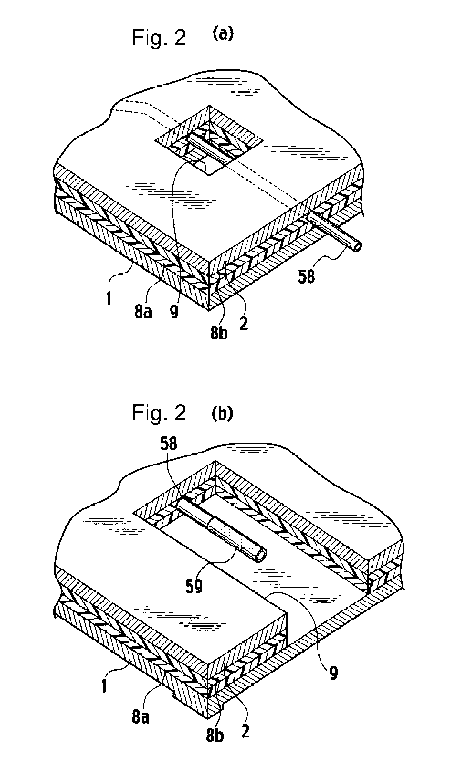
[0107]A copper foil having a thickness of 35 1 μm carrying an adhesive agent, which is non-adhesive at room temperature, S9009 (trade name, manufactured by Dow Corning Asia Co., Ltd., thickness: 200 μm) was used as the first supporting plate 1. High-performance engineering plastic tubes (material: PEEK, inner diameter: 0.2 mm, outer diameter: 0.4 mm) manufactured by Nirei Industry Co., Ltd. were placed thereon, by using a multiwire-wiring machine allowing ultrasonic vibration as well as load-output and NC control and having a movable X-Y table. A load of 80 g and ultrasonic vibration at a frequency of 30 kHz were applied to the hollow filaments 58 placed. The hollow filaments 58 were placed in the shape of circular arc of 5 mm in radius, and crossing regions were also formed. Application of the load and ultrasonic vibration was eliminated in the area close to the intersection.

[0108]A polyimide film 200H (registered trade name: Kapton) manufactured by E.I. du Pon...

example 1

[0111]An aluminum plate carrying a non-adhesive pressure-sensitive adhesive manufactured by Dow Corning Asia Co., Ltd. trade name S9009 (thickness 100 μm) and having a thickness of 0.5 mm was used as the first supporting plate. Fluoroplastic EXLON PFA tubes (trade name, inner diameter: 0.5 mm, outer diameter: 1.5 mm) manufactured by Iwase Co., Ltd., were placed as the hollow filaments, by using an NC wiring apparatus allowing ultrasonic vibration as well as load-output and NC control and having a movable X-Y table. A load of 120 g and ultrasonic vibration at a frequency of 20 kHz were applied to the hollow filaments placed, which were placed closely in the straight-line shape of 40 cm in length. No load or ultrasonic vibration was applied in the area close to the intersection.

[0112]A polyimide film 200H (registered trade name: Kapton) manufactured by E.I. du Pont de Nemours and Company as the second supporting plate was laminated over the hollow filaments by vacuum lamination.

[0113]...

example 2

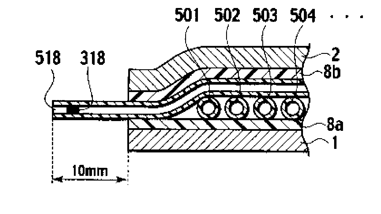
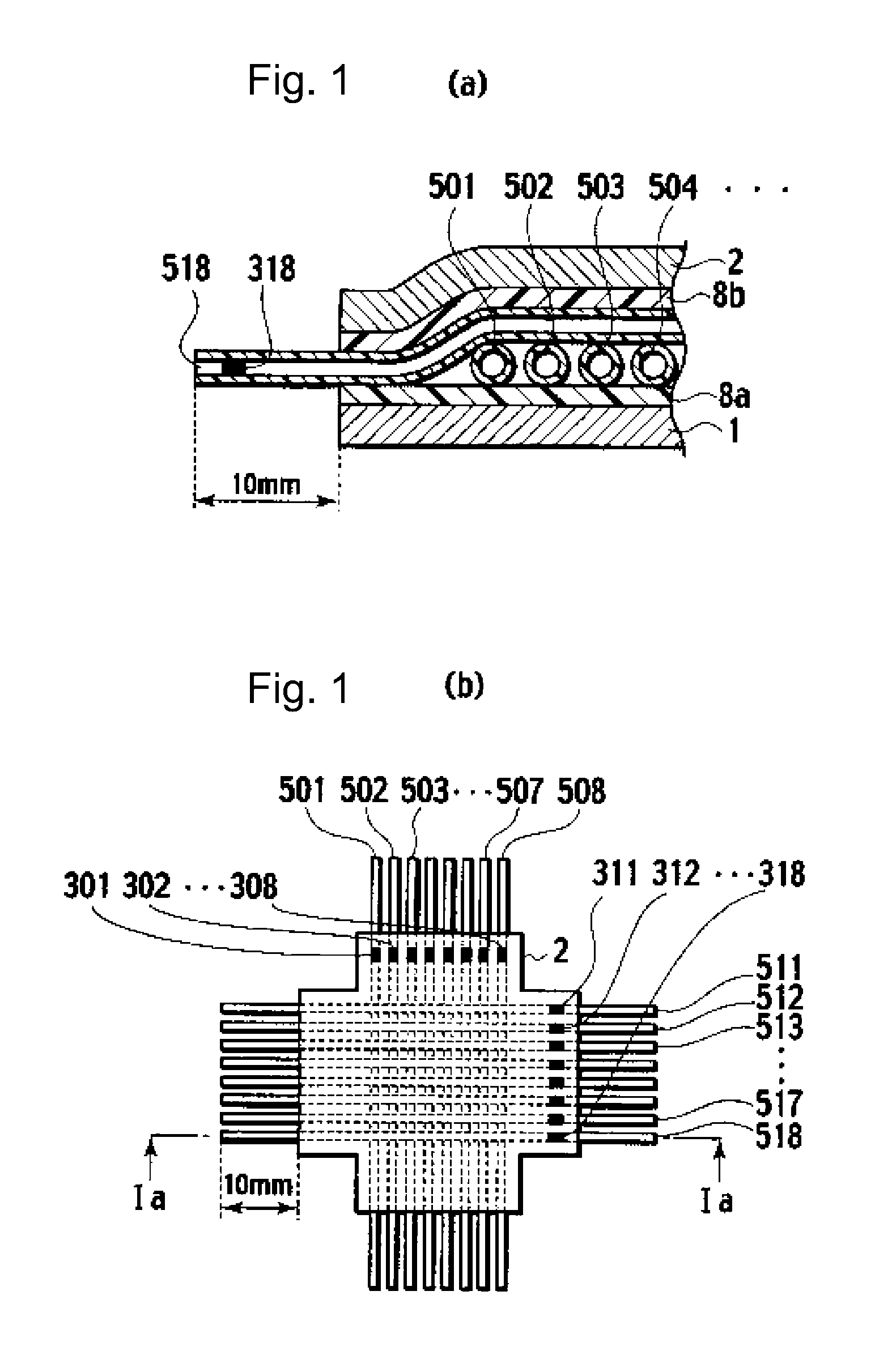
[0117]Fluoroplastic tubes (trade name: EXLON PFA tube, inner diameter: 0.5 mm, outer diameter: 1.5 mm) manufactured by Iwase Co., Ltd. were used. The tubes were cut into pieces of approximately 40 cm in length, and were fixed on particular regions 301 to 308, while a polyethylene filter was plugged into each of them from one end. 0.01 cc of a gel pack filler (trade name: TM70, manufactured by Hitachi Chemical Co., Ltd.) was packed in the tubes, to give hollow filaments 501 to 508.

[0118]An aluminum plate having a thickness of 0.5 mm carrying a non-adhesive pressure-sensitive adhesive (trade name: S9009, manufactured by Dow Corning Asia Co., Ltd., thickness: 100 μm) was used as the first supporting plate 1. The hollow filaments are placed thereon by using an NC wiring apparatus allowing ultrasonic vibration as well as load-output and NC control and having a movable X-Y table. The hollow filaments 501 to 508 were placed closely in a straight line shape of 40 cm in length, while a load ...


PUM

PropertyMeasurementUnit
inner diameteraaaaaaaaaa
pHaaaaaaaaaa
diameteraaaaaaaaaa

Abstract

The present invention provides a supporting unit of microfluid system having a smaller restriction on the number of the steps and capacity of the reaction and analysis that can be produced easily, and a microfluid-system supporting unit allowing mounting of complicated fluid circuits densely. The present invention relates to a microfluid-system supporting unit, comprising a first supporting plate and at least one hollow filament constituting the channel of the microfluid system, wherein the hollow filament is placed on the first supporting plate in any shape and a particular internal region of the hollow filament has a function.

Description

[0001]This application is a division of U.S. application Ser. No. 10 / 598,086, filed on Aug. 17, 2006, which is a 371 National Stage of International Application No. PCT / JP2005 / 002433 filed on Feb. 17, 2005.TECHNICAL FIELD[0002]The present invention relates to a supporting unit for microfluid-system.BACKGROUND ART[0003]Studies on reduction in size of reaction system and analyzer by using the MEMS (Micro Electro Mechanical System) technology are now in progress in the fields of chemistry and biochemistry. Monofunctional mechanical elements (micromachines) such as micropump and microvalve, components of such a system, have been under research and development (see, for example, Nonpatent Documents 1 and 2).[0004]Various parts such as micromachines should be systemized in multiples for a desirable chemical reaction or chemical analysis. Such systems finally obtained are generally called, for example, microreactor systems or micro-total analysis system (μTAS). The micromachine is generall...

Claims


Application Information

Patent Timeline
Patent Type & Authority Applications(United States)
IPC IPC(8): B01L3/00B01J19/00G01N1/00G01N1/10G01N37/00
CPCB01J19/0093B01L2300/1827B01J2219/00788B01J2219/00822B01J2219/00831B01J2219/00833B01J2219/0086B01J2219/00869B01J2219/00873B01J2219/00918B01J2219/00925B01L3/5027B01L3/502707B01L2300/0627B01L2300/0816B01L2300/0838B01L2300/0861B01L2300/0874B01J2219/00783G01N1/00B01J19/00G01N1/10G01N37/00
Inventor KAWAZOE, HIROSHIYASUE, KIYOSHIAKAI, KUNIHIKOINOUE, YOSHINORI
Owner RESONAC CORPORATION
Why Eureka
Try Eureka