Plasma generator for electrothermal-chemical weapon system comprising improved connectors, and method for preventing the electrical contact of the plasma generator from being broken
a technology of electrothermal-chemical weapon system and plasma generator, which is applied in the direction of weapons, electric discharge lamps, electrical equipment, etc., can solve the problems of increasing increasing the total weight, and limiting the maximum size of the propellent charge by the barrel length of the weapon, etc., to achieve accurate control, reduce the effect of heat and less stress
- Summary
- Abstract
- Description
- Claims
- Application Information
AI Technical Summary
Benefits of technology
Problems solved by technology
Method used
Image
Examples
second embodiment
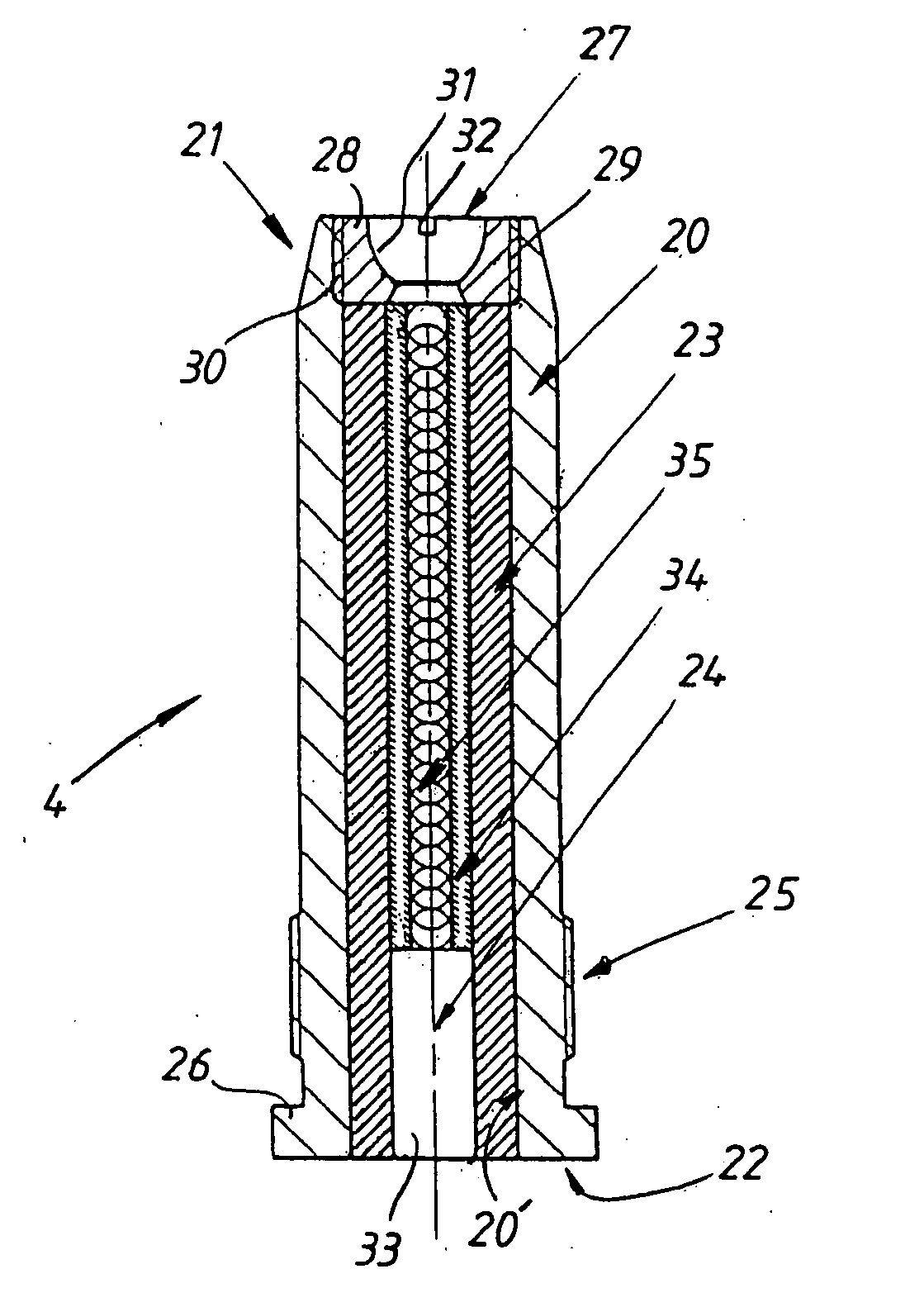
The plasma generator 4′ according to this second embodiment, FIG. 9, further comprises a somewhat differently configured center electrode 24′. The rear metallic center connector 33′ is in FIG. 9 shown somewhat axially displaced inside the ceramic tube 23 in the direction of the front cylindrical body 28, with the formation of an empty space 43 toward the rear end 22 of the combustion chamber 20, which empty space 43 is intended for the male connector 49 of the back piece 14, i.e. its input conductor 14c (schematically shown in FIG. 9 and FIG. 10), which connector 49 has a length which expediently exceeds the flange thickness, preferably has double the thickness of the flange 26′ in order to ensure a large sliding surface 52 along the radial contact surface of the male connector 49. In addition, said center connector 33′ comprises a rear centric cavity 44 extending axially inward, the inner surface 44′ of which cavity 44 is lined with the same type of lamellar contact strip 45, and w...
first embodiment
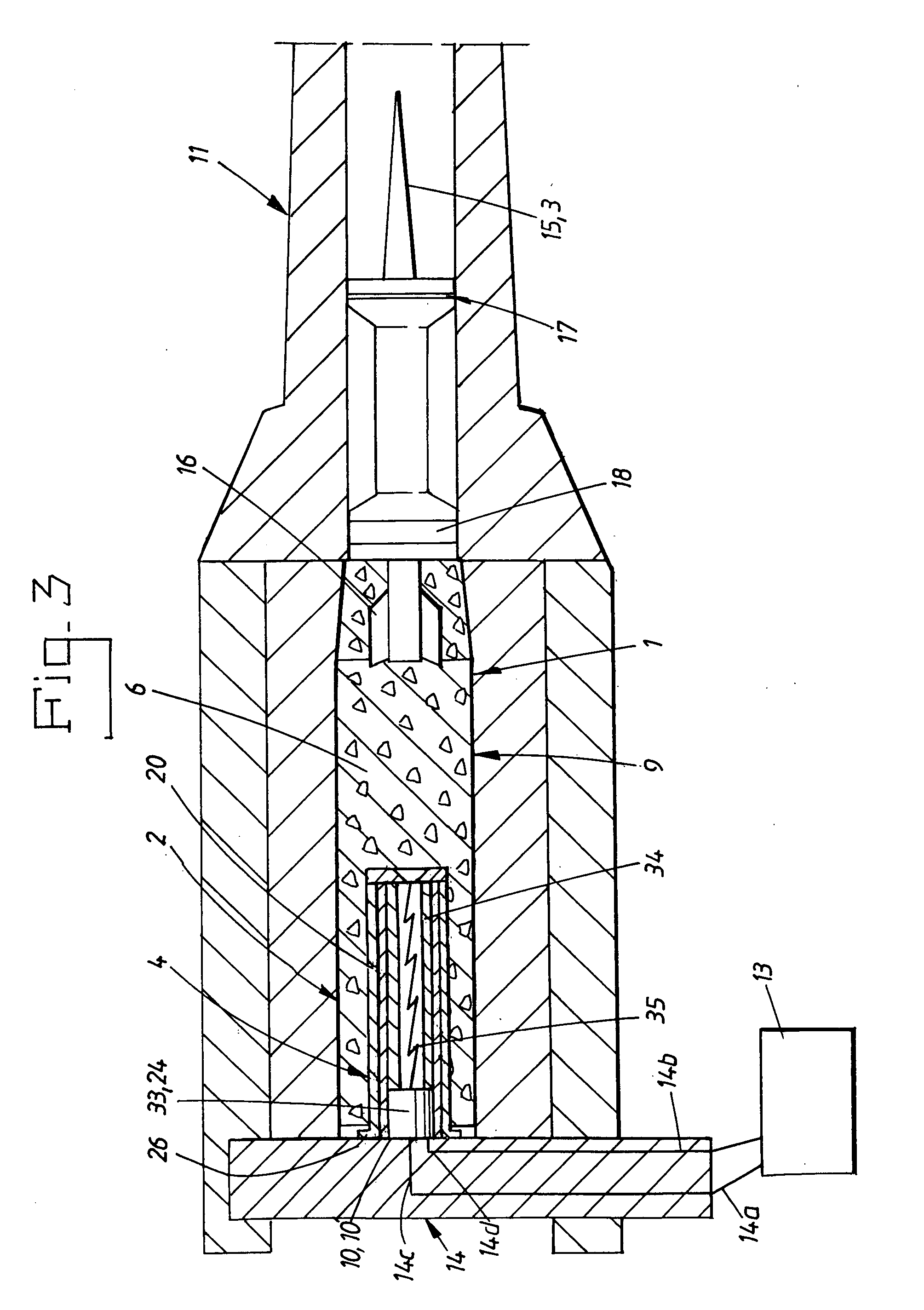
One difference with the configuration of the lamellar contacts 42″, 45″ which is shown in FIG. 9 compared with the first embodiment shown in FIG. 4 is that the first connectors 42′, 45′ on the plasma generator 4′, i.e. the outer and inner lamellar contact strips 42, 45 in FIG. 9, provide the facility for the connectors 48, 49 and the lamellar contact strips 42, 45 to be able to slide relative to each other over a certain axial distance, so that said axial clearance Z is formed, and yet be in unbroken radial contact by virtue of the sliding surface 52, 53, interacting between them, of the respective part. This configuration of the contact surface naturally provides a considerably larger contact surface than is the case with the customary contact surfaces of the point-contact or surface-contact type, so that the current transfer is spread over this larger contact surface, so that the current transfer is facilitated and the risk of a light arc is eliminated, thereby preventing welding / ...
PUM
 Abstract
Description
Claims
Application Information
 - R&D
- Intellectual Property
- Life Sciences
- Materials
- Tech Scout
- Unparalleled Data Quality
- Higher Quality Content
- 60% Fewer Hallucinations
Browse by: Latest US Patents, China's latest patents, Technical Efficacy Thesaurus, Application Domain, Technology Topic, Popular Technical Reports.
© 2025 PatSnap. All rights reserved.Legal|Privacy policy|Modern Slavery Act Transparency Statement|Sitemap|About US| Contact US: help@patsnap.com


