X-ray phase grating and method for producing the same
a phase grating and x-ray technology, applied in the field of x-ray phase gratings, can solve the problems of difficult to produce a cutting tool having a width smaller than or equal to the slit width, difficult to achieve a small pitch, and difficult to produce a large-area phase grating
- Summary
- Abstract
- Description
- Claims
- Application Information
AI Technical Summary
Benefits of technology
Problems solved by technology
Method used
Image
Examples
example 1
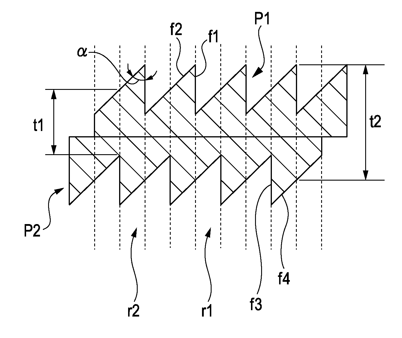
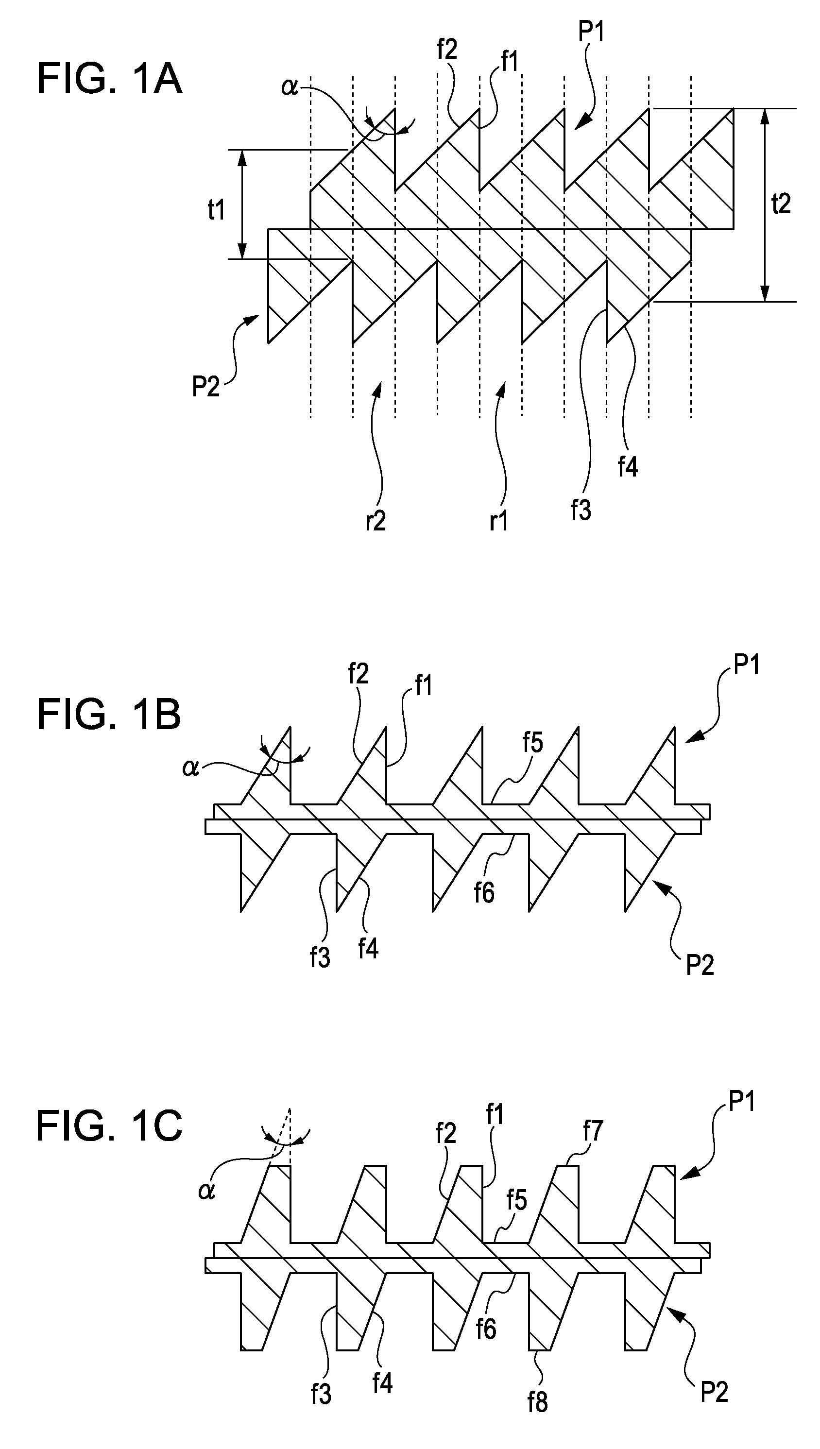
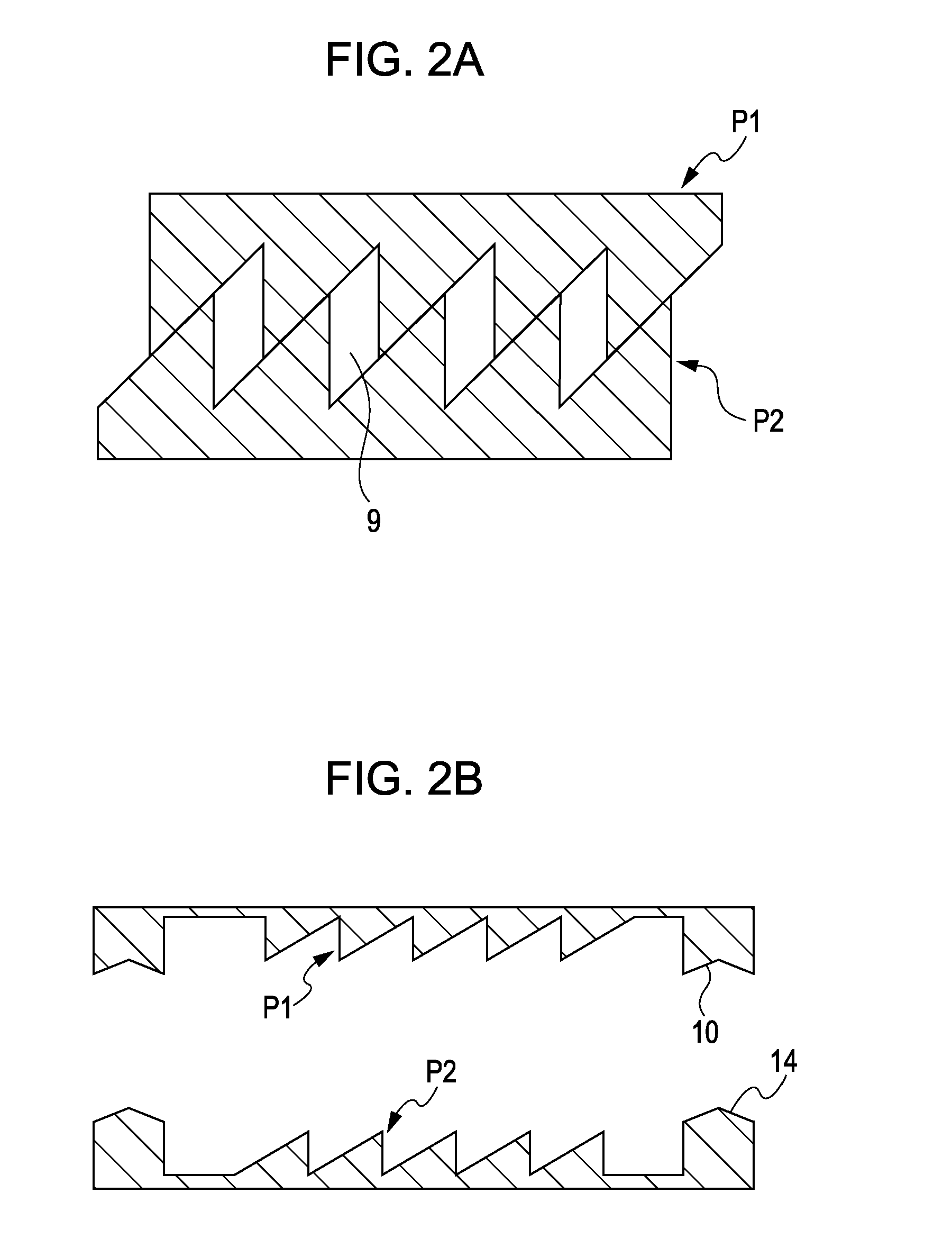
[0032]In Example 1, an example of a method for producing a phase grating by combining two substrates, each having a serrated structure on one surface thereof, so that the serrated surfaces are shifted from each other by one half period to achieve stepwise phase modulation will be described. An oxygen-free copper substrate 4 is subjected to cutting using a cutting tool 2 having an edge angle of 45° to form a serrated pattern 12 having a pitch p of 3.1 μm and a depth of 3.1 μm and including a joint portion 10. A nickel film 6 is then deposited on the oxygen-free copper substrate 4 by nickel plating and is polished to a thickness of 6.15 μm. Subsequently, the polished surface is bonded to a glass support substrate 8, and the oxygen-free copper substrate 4 is removed by dissolution (see FIGS. 5A to 5E). Similarly, a substrate having a serrated pattern 16 formed so as to be shifted by one half period and including a joint portion 14 is prepared, and the two substrates are stacked with th...
example 2
[0033]In Example 2, an example of a method for producing a phase grating by forming serrated structures on both surfaces of a substrate such that they are shifted from each other by one half period to achieve stepwise phase modulation will be described. A nickel film 6 is deposited on an oxygen-free copper substrate 4 subjected to cutting as in Example 1 by nickel plating, and the same serrated pattern as that of the oxygen-free copper substrate 4 is formed on the nickel film 6 such that they are shifted by one half period, where the thickest portion has a thickness of 12.3 μm. After the oxygen-free copper substrate 4 is removed by dissolution, the nickel film 6 is covered and sealed with resin support substrates 8. Thus, a phase grating that causes a phase shift of π / 2 for 17.4 keV X-rays is obtained (see FIG. 9B). In FIG. 9B, a substrate 20 having a first pattern and a second pattern on either side thereof is shown.
example 3
[0034]In Example 3, another example of a method for producing a phase grating by combining two substrates, each having a serrated structure on one surface thereof, so that the serrated surfaces are shifted from each other by one half period to achieve stepwise phase modulation will be described. As in Example 1, the oxygen-free copper substrate 4 is subjected to cutting to form a structure 12′ complementary to a serrated pattern 12 having a pitch of 11.1 μm and a depth of 11.1 μm. As the transfer material 22, an SU-8 photoresist manufactured by Kayaku Microchem Corporation is applied to a glass substrate 24, and the template pattern is transferred thereto by injection molding. After the photoresist is cured by ultraviolet irradiation through the glass substrate 24, the template is removed. Thus, the serrated pattern 12 including the joint portion 10 is obtained (see FIGS. 7A to 7D). In the removal step, the serrated template is advantageous over a rectangular template in that the se...
PUM
| Property | Measurement | Unit |
|---|---|---|
| height h1 | aaaaa | aaaaa |
| thickness t2 | aaaaa | aaaaa |
| thickness t2 | aaaaa | aaaaa |
Abstract
Description
Claims
Application Information
 - R&D
- Intellectual Property
- Life Sciences
- Materials
- Tech Scout
- Unparalleled Data Quality
- Higher Quality Content
- 60% Fewer Hallucinations
Browse by: Latest US Patents, China's latest patents, Technical Efficacy Thesaurus, Application Domain, Technology Topic, Popular Technical Reports.
© 2025 PatSnap. All rights reserved.Legal|Privacy policy|Modern Slavery Act Transparency Statement|Sitemap|About US| Contact US: help@patsnap.com


