Dual mode continuously variable transmission

a transmission and continuously variable technology, applied in the direction of gearing control, gearing elements, gearing rings, etc., can solve the problems of reducing the effective diameter of the pulley, energy loss, and the inability of the cvt to effectively endure the high engine power, and achieve excellent running performance, excellent mileage, and the durability of the relationship. deteriorate

Inactive Publication Date: 2011-03-03
KANG MYUNGKOO +3
View PDF10 Cites 19 Cited by
  • Summary
  • Abstract
  • Description
  • Claims
  • Application Information

AI Technical Summary

Benefits of technology

[0018]Accordingly, the present invention has been made keeping in mind the above problems occurring in a high-speed transmission mode of a conventional CVT and the present invention is intended to propose a dual mode continuously variable transmission (DMCVT), which can control the input-side variable speed pulley such that the diameter of the pulley in a high-speed transmission mode does not increase over a predetermined range, and which can efficiently output rotatory force within a desired range, thus preventing power loss caused by belt slip, preventing a reduction in durability of the belt and the pulleys and energy loss caused by a quick increase in friction heat generated between the belt and the pulleys, and preventing breakage of important parts related to belt driving.
[0023]The dual mode continuously variable transmission (DMCVT) of the present invention solves the problem of a performance reduction, which may be experienced in a high-speed transmission mode of a conventional CVT. Described in detail, in a low-speed transmission mode of the conventional CVT, wherein the diameter ratio of two variable speed pulleys is set to a level suitable for the function as a reducer, the conventional CVT provides excellent mileage and excellent running performance. However, in a high-speed transmission mode of the conventional CVT, wherein the diameter ratio of the two variable speed pulleys is set to a level suitable for the function as an accelerator, the rotatory speed of the belt exceedingly increases, thus generating slip of the belt over the pulleys and producing friction heat between the belt and the pulleys, thereby deteriorating durability of related parts and causing energy loss. However, the present invention is configured such that the diameter ratio between the pulleys in a high-speed transmission mode can be set to a level suitable for the function as a reducer, so that the present invention can solve the above-mentioned problems of the conventional CVT.
[0024]In other words, in a low-speed transmission mode, the first mode having a gear ratio of 1:1 is selected, while, in a high-speed transmission mode, the second mode having a gear ratio of 2˜1:1 is selected prior to output of rpm, so that it is possible to realize output of desired rpm without exceedingly increasing the diameter of the input-side variable speed pulley. Accordingly, the advantages, expected from the conventional CVT in a low-speed transmission mode, can be achieved by the CVT of the present invention in a high-speed transmission mode. Therefore, the CVT of the present invention can realize economic efficiency and excellent running performance.
[0025]Further, in the CVT of the present invention, the diameter ratio between the two variable speed pulleys for realizing high speed output power can be maintained at the same level as that of a typical reducer, so that the variable sizes of the variable speed pulleys can be reduced compared to a conventional CVT. The reduction in the size of the pulleys provides advantages of reducing the manufacturing cost of the transmission, reducing the volume and improving the mileage.
[0026]Due to the above-mentioned advantages of the present invention, i.e. improvements in the durability of the belt, the variable speed pulleys, the hydraulic controller and the parts related to them and an improvement in energy efficiency, the CVT can be adapted to a large-sized car having a large amount of exhaust in addition to a small-sized car, so that the advantages will contribute to a considerable enlargement of the CVT applications.
[0027]Further, when the present invention is adapted to a parallel hybrid car which has been drawing attention in recent years, the CVT can function as a transmission having high efficiency, so that the present invention can realize improvements in the durability and energy efficiency of the parallel hybrid car and can contribute to the considerable development of the related industries.

Problems solved by technology

On the contrary, when the distance between the opposite rims of each pulley increases, the belt contact surface in the pulley moves inwards in radial directions, thus reducing the effective diameter of the pulley.
However, the CVT has small allowable limits for torques of the variable speed pulleys and the belt, so that the CVT has been mainly adapted to small-sized cars.
This is because of the fact that, when the CVT is used in a car having high engine power, the CVT can not effectively endure the high engine power.
Further, the CVT has a small allowable limit for the torque related to belt tension and easily generates heat due to slipping and friction between the belt and the pulleys during the high speed running mode of a car, thereby resulting in energy loss and a reduction in the expected lifespan of the belt, and also it causes additional energy loss due to a hydraulic controller used for driving the variable speed pulleys.
Therefore, the applications of CVTs are limited.
Although CVTs have higher mileage and energy efficiency in comparison to conventional automatic transmissions, the energy efficiency of the CVT is lower than that of conventional manual transmissions.
However, this mileage of the NEW SM3 is still lower than the mileage of 16.3 km / l of models using conventional manual transmissions.
Although the CVT realizes soft acceleration and suits frequent speed change and low-speed operation of a car in the center of a city, the CVT is problematic in that the mileage thereof is lower than that of another type of transmission that uses gears in the case of steady operation at high speed, for example, in the case of being operated on a highway on which cars may maintain a high speed not lower than 100 km / h steadily, realized by a transmission mode of 5 or more stages.
Although the CVT had been in fashion due to the advantages of volume, price and durability for a while in the past, the applications of the CVT are limited to small-sized cars due to the above-mentioned problems.
Although the CVT is problematic in that it is not suited for high-speed operation and results in quick abrasion of the belt, the CVT luckily is suited to operation in the center of a city, in which it is required to frequently change the speed in low-speed transmission mode, such as a transmission mode of 1-, 2- or 3-stage, and suits low-speed operation, so that the CVT may have an effect on improvements in mileage.
However, in the case of high-speed operation, the expected lifespan of the belt in the CVT is reduced due to slipping and friction between the belt and pulleys and the energy efficiency of the CVT is reduced.
In a conventional transmission, when a shift gear is changed from a low stage to a high stage so as to increase the running speed of a car, there inevitably exist both shift shock and shift lag in the transmission.
However, when the motor rpm in the above state is low, the motor may not efficiently aid the engine operation, but imposes a load on the engine.
When the motor rpm in the above state is exceedingly high, the motor undesirably causes a waste of energy to reduce energy efficiency although the motor may aid a little increase in the engine rpm.
However, in the case of constant running at a high speed, the mileage of the parallel hybrid car using the CVT is still lower than that of a car using a conventional transmission.
However, when battery charging has been completed, the function of the motor as the generator is meaningless, and the presence of the motor undesirably impose a load on the car.
As described above, although the CVT realizes high mileage and high running performance in low-speed transmission mode, the CVT is problematic in high-speed transmission mode.
When the linear velocity of the belt increases exceedingly as described above, the belt frequently slips over the belt contact surfaces of the pulleys, thus resulting in power loss and generating friction heat caused by friction between the belt and the pulleys, thereby deteriorating energy efficiency.
This also has serious negative effects on the expected lifespan of the belt and the pulleys.

Method used


Image

  • Dual mode continuously variable transmission
  • Dual mode continuously variable transmission
  • Dual mode continuously variable transmission

Examples


first embodiment

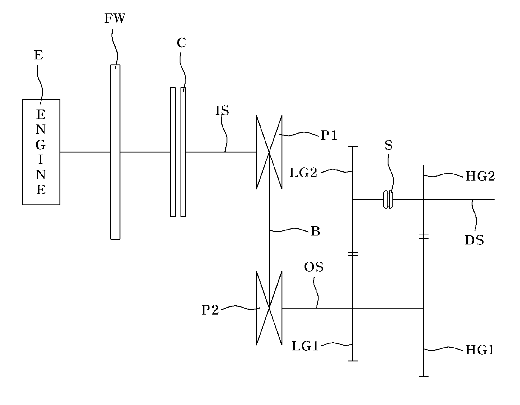
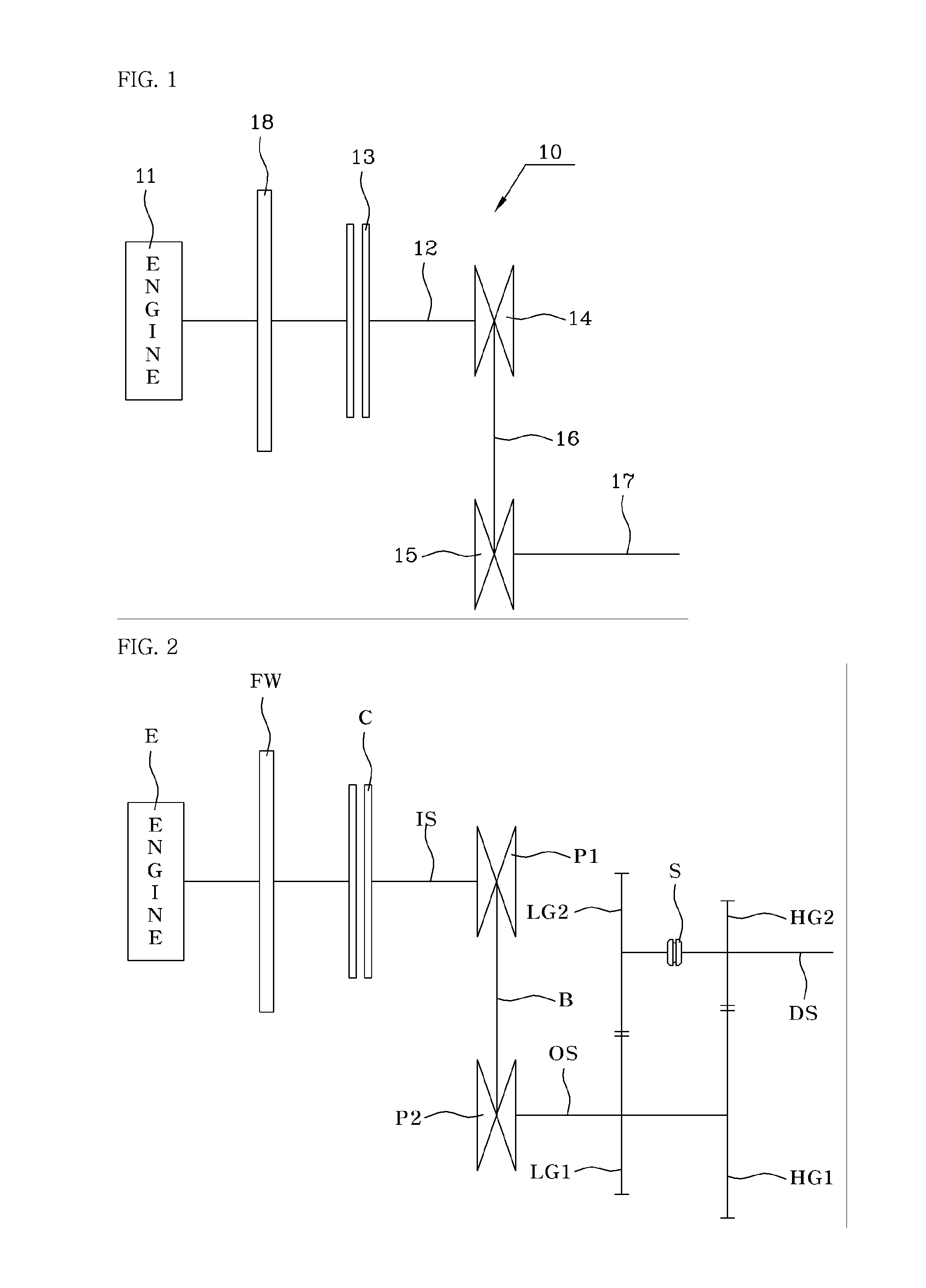
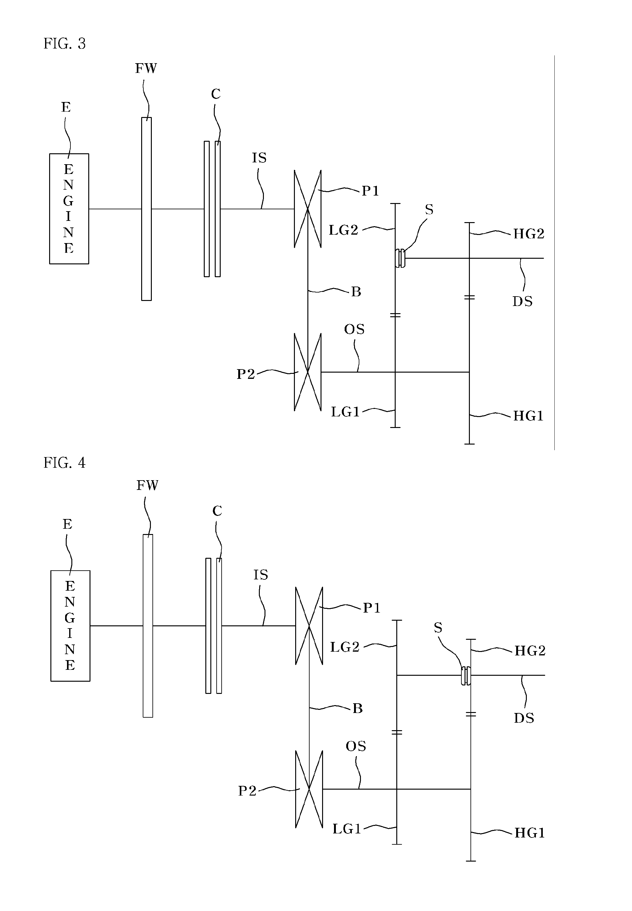
[0036]FIG. 2 through FIG. 4 are diagrams schematically illustrating the construction and power transmission mechanism of a continuously variable transmission (CVT) according to the present invention. Like a conventional CVT, the dual mode continuously variable transmission (DMCVT) according to the present invention comprises two pulleys P1 and P2 and a belt B, with gears LG1, LG2, HG1 and HG2 coupled to the pulleys for changing through the gear ratios between dual modes.

fourth embodiment

[0037]A clutch C for controlling speed change operation of the CVT is provided on an input shaft IS which directly receives a rotatory force from an engine E, a drive variable speed pulley P1 is mounted on the input shaft, and a driven variable speed pulley P2 is mounted on an output shaft OS. The power transmission from the drive variable speed pulley P1 to the driven variable speed pulley P2 is realized by the belt B. It is preferred that the belt B be a metal belt. In the drawing, the reference character FW denotes a flywheel. Further, the clutch C may be selected from conventional dry type clutches, but the type of the clutch C is not limited to the dry type clutches. In other words, the clutch C may be selected from wet type clutches or torque converters generally used in conventional automatic transmissions. In the case of a torque converter used as the clutch C, the structure of the torque converter will be described in the description for the present invention.

[0038]Addition...

second embodiment

[0061]FIG. 5 is a diagram schematically illustrating the construction and power transmission mechanism of a CVT according to the present invention.

[0062]In the second embodiment, the synchro selector S is mounted on the output shaft OS other than the drive shaft DS, and selects gears of either the first mode or the second mode. The mechanism and function of the DMCVT according to the second embodiment except for the above-mentioned difference remains the same as those of the DMCVT according to the first embodiment and further explanation of the mechanism and function of the second embodiment is deemed not necessary.

[0063]FIG. 6 is a diagram schematically illustrating the construction and power transmission mechanism of a CVT according to a third embodiment of the present invention. In the third embodiment, gear trains for changing the gear ratios between first and second modes are arranged in front of the variable speed pulleys. Described in detail, a clutch C is mounted to a first ...


PUM


Abstract

A dual mode continuously variable transmission (DMCVT), which can maintain advantages of a reducer operated in low-speed running mode and makes the diameter ratio of variable speed pulleys in high-speed transmission mode act as a reducer, thus improving durability and energy efficiency of the CVT. The DMCVT has a drive variable speed pulley mounted on an input shaft connected to an engine, a driven variable speed pulley mounted on an output shaft and receiving a rotatory force from the drive pulley through a belt, a drive shaft, first and second mode output gears mounted on the output shaft, first and second mode drive gears mounted on the drive shaft and gearing into the first and second mode output gears, respectively, and a synchro selector selectively engaging with a gear of one of the drive and driven shafts.

Description

BACKGROUND OF THE INVENTION[0001]1. Field of the Invention[0002]The present invention relates, in general, to continuously variable transmissions (CVT) and, more particularly, to a dual mode continuously variable transmission (DMCVT), which has a pair of variable speed pulleys and dual mode gear trains coupled to the pulleys so as to transmit engine power, thus preventing belt slip, friction heat, shift shock and hydraulic pressure loss which may be generated in a conventional CVT operating in high-speed transmission mode.[0003]2. Description of the Related Art[0004]A continuously variable transmission (CVT) is a transmission which can change steplessly through an almost infinite number of effective gear ratios within a predetermined range of transmission modes. Because the CVT contrasts with another type transmission, which can change through a limited number of effective gear ratios, the CVT is a so-called “stepless transmission”. The CVT can drive an engine at the most efficient ...

Claims


Application Information

Patent Timeline
Patent Type & Authority Applications(United States)
IPC IPC(8): F16H7/00F16H61/662
CPCF16H37/021F16H9/04F16H55/36F16H55/52
Inventor KANG, MYUNGKOOJEON, HYO JEONGKANG, SEUNGMOKANG, SUEJEONG
Owner KANG MYUNGKOO
Why Eureka
Try Eureka