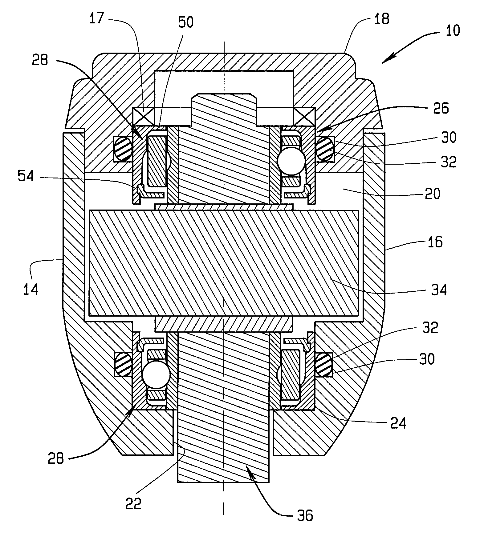
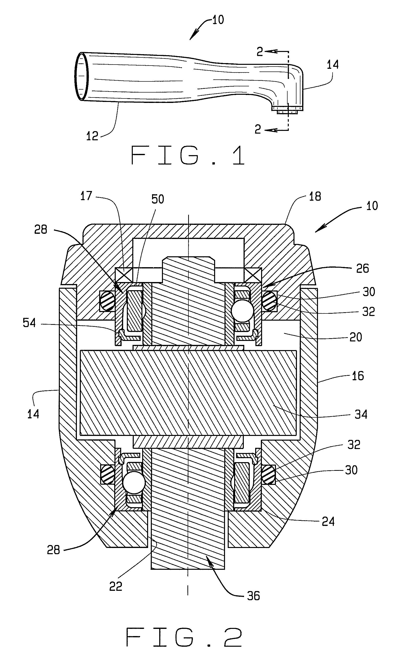
[0008]Briefly stated, the present disclosure provides a bearing assembly for use in a medical, surgical, or dental handpiece that enables spindle rotation for a supported rotary tool at high speeds which may approach 500,000 rpm in dental handpieces. The bearing assembly incorporates annular gap shields at each axial end to prevent contaminate ingress and to retain lubricating
grease within the bearing assembly to avoid re-
lubrication after each use or sterilization cycle.
[0009]In one embodiment, the bearing assembly comprises an inner ring, an outer ring, a plurality of stainless steel or
ceramic balls, and a
retainer that separates the balls. The bearing assembly has an angular contact design, whereby one of the rings is relieved for assembly, and the
retainer is a one-piece design which fully encompasses the
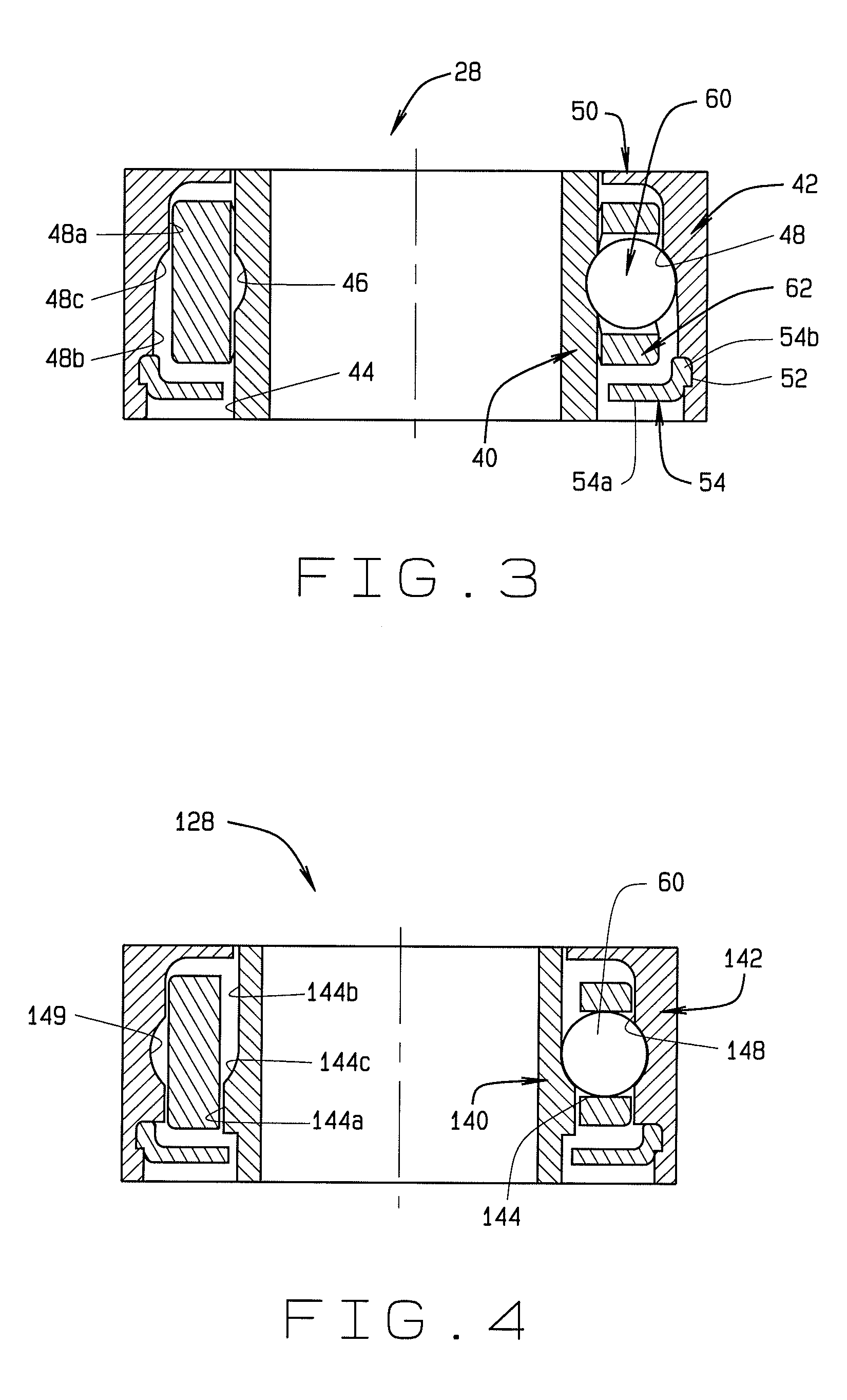
equator of each ball. The retainer cannot be assembled into the bearing after the rings and balls are assembled, and the retainer is necessarily of a “non-crown” or “non-pronged” design. The bearing assembly further includes two shield closures, with the first shield preferably integral to the inner or outer ring, or non-integral and attached to the bearing in some other way. The first single shield is disposed to protect the interior of the bearing assembly from external debris and contaminates, with the shield directly adjacent to the exterior openings of the housing. The second shield, is mounted to either the inner or outer ring on either the ID or OD of the ring such that the original standard bearing
chassis cross-section is not changed. The second shield is positioned between the interior of the bearing assembly (balls, retainer, and
grease) and the driven member or rotary tool, without altering the external configuration of the bearing assembly. This second shield substantially encloses the annular gap between the inner and outer bearing rings, and prevents
forced air that drives the
turbine from driving
lubricant out of the bearing assembly. The second shield also prevents ingress of cleaning solutions, foreign material, and
contamination into the bearing that can compromise, degrade, dissolve, or otherwise remove the initial lubricant from the bearing. In non-air-turbine powered handpieces, the second shield encloses the interior of the bearing assembly more effectively than a single shield design, thus retaining factory-applied grease lubricant more effectively than prior art designs. The bearing can be sized for use in a variety of medical or dental handpiece applications.
[0010]In an embodiment of the present disclosure, the second shield component of the bearing assembly is a molded or machined component comprised of an
engineering plastic (or
polymer), composite or other material, such as an amorphous
polyetherimide, with or without a glass filler. The second shield is capable of withstanding repeated sterilization, autoclaving, and
exposure to associated high temperatures without degradation of mechanical properties, while maintaining a rigid barrier, and while preserving shield integrity.
[0011]In an embodiment of the present disclosure, the second shield component of the bearing assembly is configured as a “snap” shield, such that it will mechanically
interlock with the inner bearing ring in an operational position, such as by snapping over a grove on the bearing ring outer
diameter, or mechanically
interlock with the outer bearing ring, such as by snapping into a groove on the bearing ring inner
diameter. The “snap” mechanical
interlocking approach eliminates the need for other fastening methods such as
welding or affixing the shield with wire and provides for easy assembly. The shield is preferrably made of an
engineering plastic material that will elastically deflect sufficiently during installation to permit a “snap” mechanical
interlocking action which return the shield to an undeflected configuration when the shield is disposed at the operational position.
[0012]In an embodiment of the present disclosure, the retainer (cage) component of the bearing assembly is composed of an
engineering plastic with a composition selected to withstand repeated sterilization and autoclaving procedures and temperatures without degradation of mechanical or tribological properties, similar to the second shield component.
[0013]In one embodiment, the retainer (cage) component of the bearing assembly is composed of a base material such as
polyamide-
imide (PAI), containing fillers including carbon (
graphite or carbon
fiber) present in amounts equal to, or greater than 10% of the component weight, and
fluoropolymer particles in amounts equal to, or greater than, 1% of the component weight. The
fluoropolymer particles may be
polytetrafluoroethylene (PTFE, such as Teflon™). The presence of fillers enhance the tribological performance (
low friction and wear) of the retainer.

