

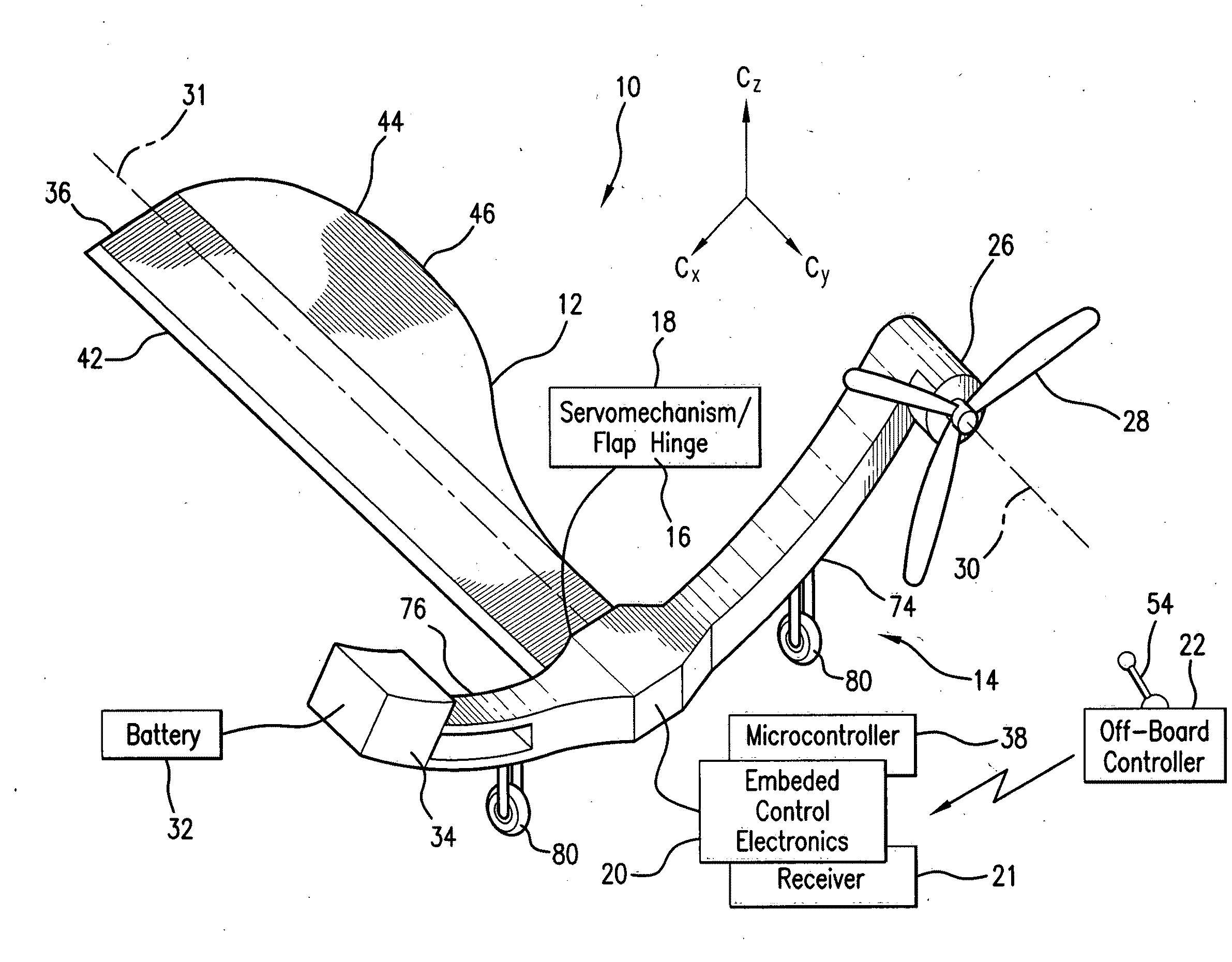
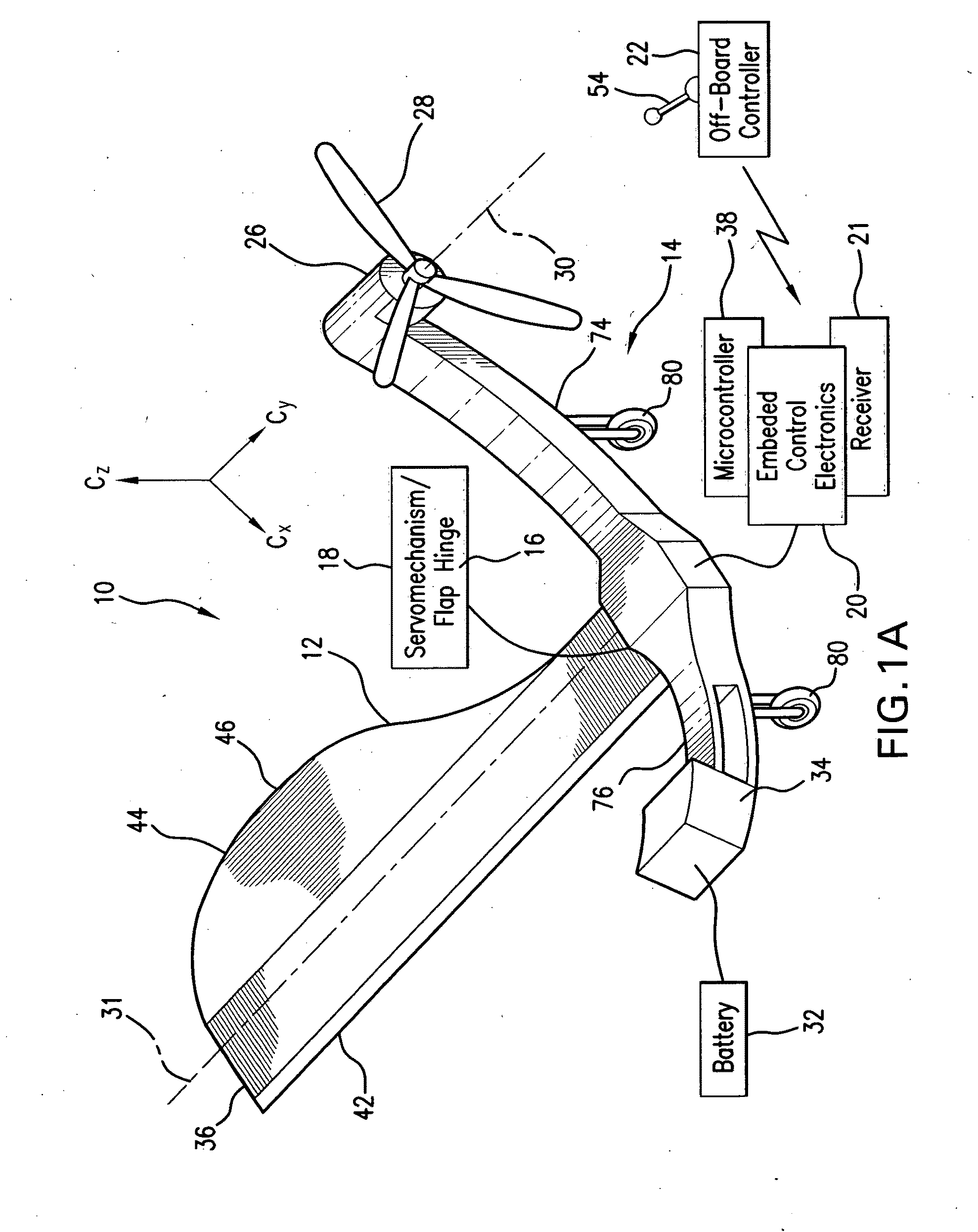
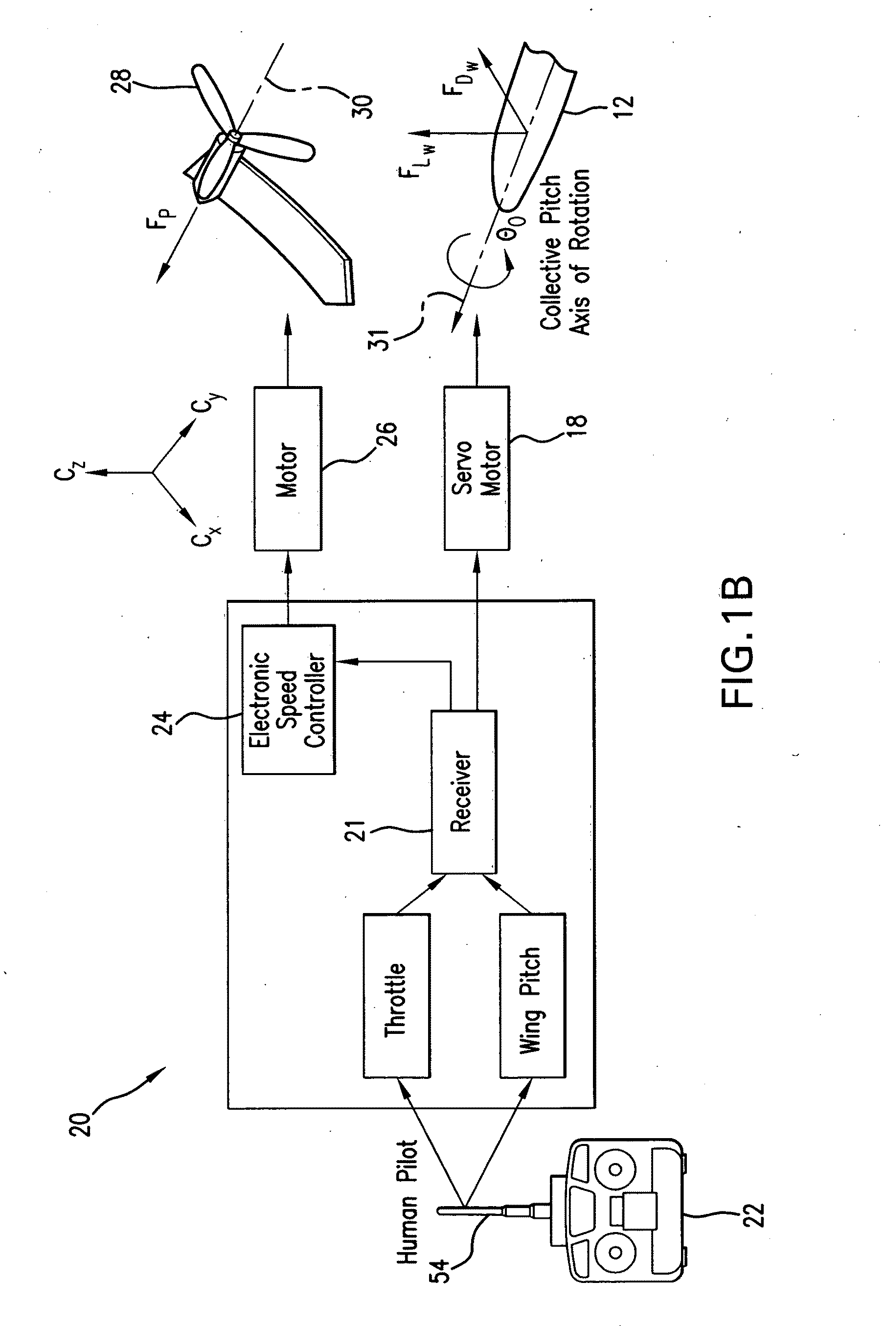
Controllable miniature mono-wing aircraft
a miniature mono-wing aircraft and control technology, applied in the direction of rotors, vessel parts, vessel construction, etc., can solve the problems of limiting the functionality of forward flight in cluttered environments, attempting to use the most basic mode, and the dynamic model of a single-winged rotorcraft has not been developed, so as to achieve low power consumption and high level of autonomy
- Summary
- Abstract
- Description
- Claims
- Application Information
AI Technical Summary
Benefits of technology
Problems solved by technology
Method used
Image

Examples
Embodiment Construction
[0087]A=dynamics matrix[0088]B=control matrix[0089]C=output matrix[0090]dy=differential element[0091]FCF=centrifugal force[0092]FG=gravity force[0093]Fp=propulsive force[0094]FWD=drag force[0095]FWL=lift force[0096]Gp(s)=plant transfer function[0097]Ix, Iy, Iz=principal moments of inertia[0098]K=static gain[0099]K(s)=controller[0100]Kd=derivative gain[0101]Kt=integral gain[0102]Kp=proportional gain[0103]p, q, r=rotational velocities[0104]RBF=transforms fixed frame F to body frame B[0105]Rxx=input autospectral density[0106]Rxy=input / output cross-spectral density[0107]Ryy=output autospectral density[0108]Tpl=time constant[0109]u, v, w=translational velocities[0110]W(s)=heave transfer function[0111]{dot over (ω)}=heave acceleration[0112]X=state vector[0113]x, y, z=inertial frame position[0114]Y=control input[0115]Yd=reference value[0116]Zω=heave stability derivative[0117]Zθ0=collective pitch stability derivative[0118]β=coning angle[0119]εi=infinitesimal quantity[0120]Θ(s)=c...
PUM
 Abstract
Description
Claims
Application Information