
Quadropole Mass Spectrometer

a mass spectrometer and quadripole technology, applied in mass spectrometers, stability-of-path spectrometers, separation processes, etc., can solve the problems of deteriorating detection sensitivity, reducing the amount of ions arriving at the detector, and unable to detect part of the target ions, so as to improve quantitative analysis capability, detection sensitivity can be higher, and detection sensitivity can be kept approximately constant

Active Publication Date: 2011-03-17
SHIMADZU CORP
View PDF11 Cites 10 Cited by
  • Summary
  • Abstract
  • Description
  • Claims
  • Application Information

AI Technical Summary

Benefits of technology

[0013]Although the conventional technique disclosed in Patent Document 1 is an efficient method, it is required these days for a scanning rate to be increased more than ever before, and the method in some cases does not satisfactorily work for such recent demands. The present invention has been made in view of such problems, and an object of the present invention is to provide a quadrupole mass spectrometer capable of preventing detection sensitivity from being deteriorated even when the scanning rate is increased, thereby achieving high analytical sensitivity and analytical accuracy.Means for Solving the Problems

Problems solved by technology

However, the increase in the scanning rate causes the following problems: Consider the case where the necessary time for a certain ion to pass through the space in the longitudinal axis direction of the quadrupole mass filter 3 is “t”.
However, if the amount of voltage change ΔV is non-negligibly increased by increasing the scanning rate, there is the possibility that a part of the target ions cannot pass through the quadrupole mass filter 3.
This causes a decrease in the amount of ions arriving at the detector 4, thereby deteriorating the detection sensitivity.

Method used


Image

  • Quadropole Mass Spectrometer
  • Quadropole Mass Spectrometer
  • Quadropole Mass Spectrometer

Examples


Embodiment Construction

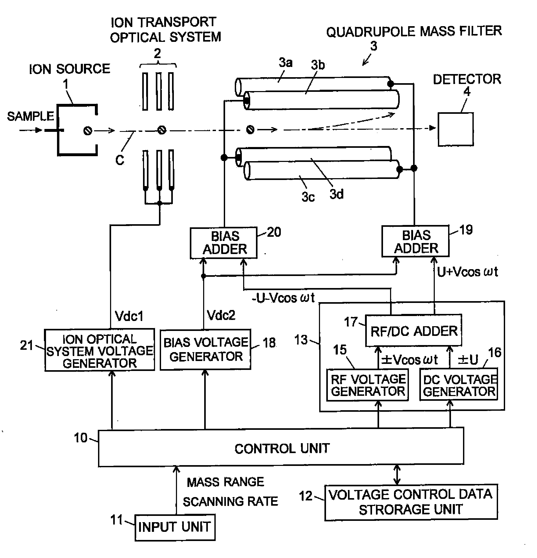
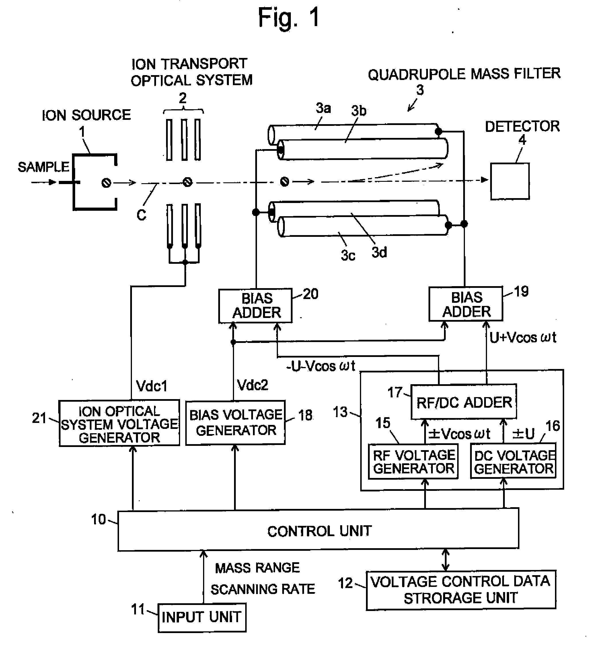
[0056]A quadrupole mass spectrometer according to an embodiment of the present invention is described, referring to the attached drawings. FIG. 1 is a configuration diagram showing main parts of the quadrupole mass spectrometer according to the present embodiment. The same reference numerals are allotted to the same structural elements as those in already described in FIG. 6. The quadrupole mass spectrometer according to the present embodiment is so configured as to introduce a sample in the form of gas into an ion source 1, and a gas chromatograph can be connected in a previous stage of the mass spectrometer. When a configuration for analyzing a sample in the form of a liquid is adopted, an atmospheric pressure ion source, such as an electrospray ionization source, is used as the ion source 1, which is set at an atmosphere approximately at atmospheric pressure, and a multistage differential exhaust system is adopted in order to arrange a quadrupole mass filter 3 and a detector 4 in...


PUM


Abstract

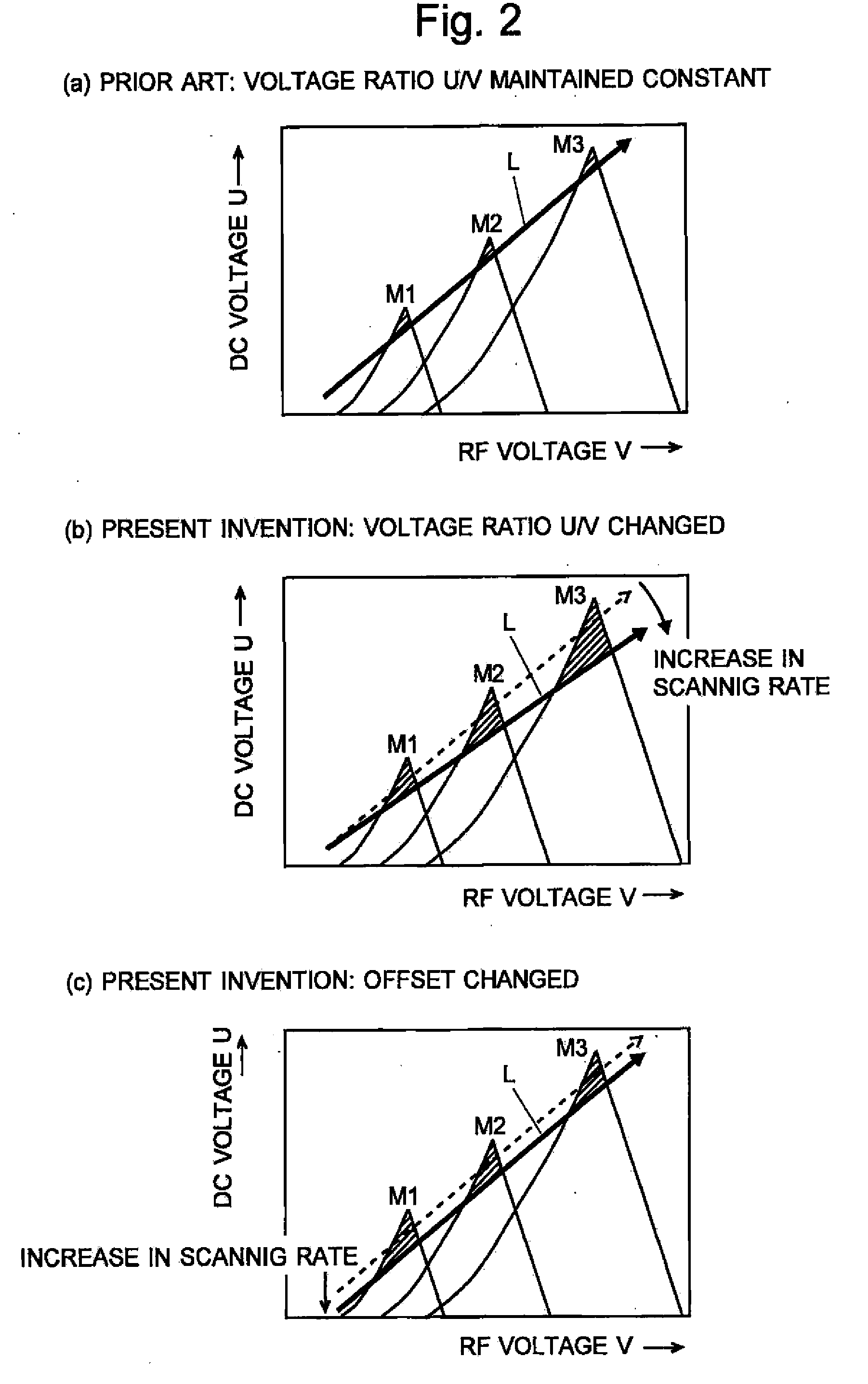
If a scanning rate of a mass scanning is set to be high, the amount of change in an applied voltage between a time of an incidence of a certain ion into a quadrupole mass filter and a time of an emission of the ion therefrom increases. This leads to a change in the condition of a passage of ions, causing the amount of ions to decrease and thereby deteriorating detection sensitivity. In order to avoid this problem, according to the present invention, the values of direct current voltage U and an amplitude V of radio-frequency voltage, both voltages being applied to rod electrodes during a mass scanning, are respectively determined so that a voltage ratio U / V of the voltage U to the amplitude V becomes smaller as the scanning rate becomes higher. Accordingly, in a stability diagram based on the Mathieu equation, the inclination of line L indicating the change in the applied voltage during the mass scanning becomes gradual and the amount of ions passing through the quadrupole mass filter increases particularly when the mass is high.

Description

TECHNICAL FIELD[0001]The present invention relates to a quadrupole mass spectrometer using a quadrupole mass filter as a mass analyzer which separates ions depending on their mass (m / z, in the precise sense).BACKGROUND ART[0002]As one type of mass spectrometers, a quadrupole mass spectrometer has been known in which a quadrupole mass filter is used as a mass analyzer which separates ions depending on their mass. FIG. 6 is a schematic configuration diagram of a typical quadrupole mass spectrometer, which mainly shows an ion optical system of the mass spectrometer.[0003]A sample molecule is ionized in an ion source 1. Generated ions are converged (also accelerated in some cases) by an ion transport optical system 2, such as an ion lens, and introduced into a space in the longitudinal axis direction of a quadrupole mass filter 3. The quadrupole mass filter 3 includes four rod electrodes arranged in such positions as to be parallel to one another around an ion optical axis C (In FIG. 6,...

Claims


Application Information

Patent Timeline
IPC IPC(8): H01J49/42H01J49/00
CPCH01J49/429H01J49/4215
Inventor MUKAIBATAKE, KAZUO
Owner SHIMADZU CORP
Learn More