Power supply device, lamp fitting, and vehicle

a technology of power supply device and lamp fitting, which is applied in the direction of electric variable regulation, process and machine control, instruments, etc., can solve the problems of large current ripple, unnecessary radiation noise, and large current ripple in the current flowing therethrough, and achieves small ripple, high efficiency, and convenient use.

Active Publication Date: 2011-03-17
PANASONIC CORP
View PDF15 Cites 30 Cited by
  • Summary
  • Abstract
  • Description
  • Claims
  • Application Information

AI Technical Summary

Benefits of technology

[0026]In accordance with the present invention, it becomes possible to provide the power supply device, which is capable of coping with the semiconductor light source loads to be set in various ways, and has high efficiency, in which the current to be supplied to each of the loads has a small ripple. Moreover, it becomes possible to provide a system, which is more functional and inexpensive, in such a manner that the power supply device of the present invention is used for the lamp fitting for the vehicle.

Problems solved by technology

Therefore, the load such as the semiconductor light source has characteristics that a large current ripple is prone to occur in the current flowing therethrough even if a voltage to be supplied thereto only has a small ripple component.
This matter also results in that a current having a large ripple component flows through a wire connected to the load, also leading to an occurrence of unnecessary radiation noise.

Method used


Image

  • Power supply device, lamp fitting, and vehicle
  • Power supply device, lamp fitting, and vehicle
  • Power supply device, lamp fitting, and vehicle

Examples


embodiment 1

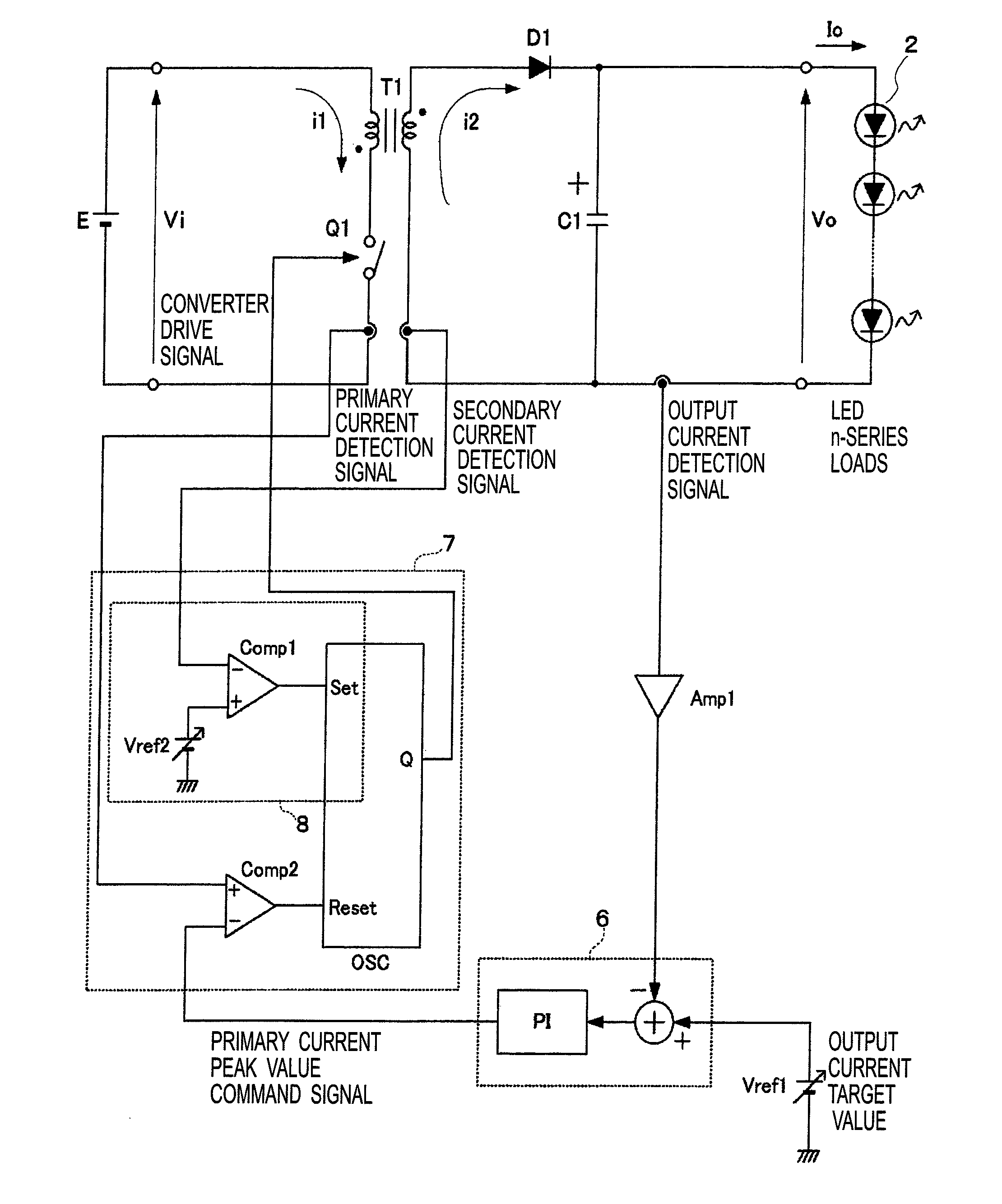
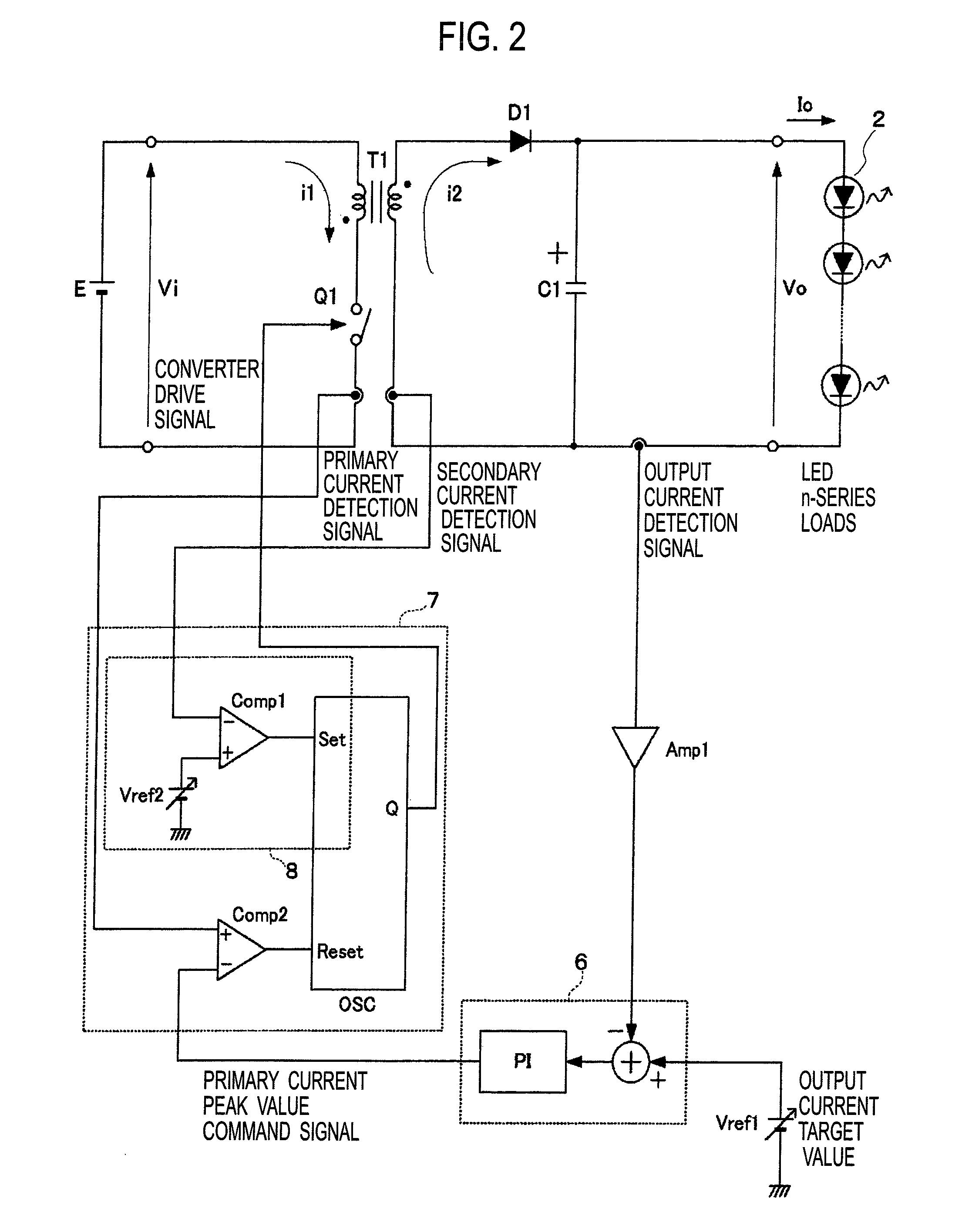
[0047]A circuit diagram of Embodiment 1 of the present invention is illustrated in FIG. 2, and an operation waveform chart thereof is illustrated in FIG. 3. By using FIGS. 2 and 3, a description is made of a specific content of this embodiment.

[0048]In this embodiment, the DC-DC converter is a flyback-type converter including a transformer T1, a switching element Q1, a rectifying diode D1, and a smoothing capacitor C1. A load 2 to be connected to the DC-DC converter is an LED load in which a plurality of LED elements are connected in series to one another.

[0049]A description is made of basic operations of the DC-DC converter. When the switching element Q1 is on, a current i1 flows from the power source E through a primary side of the transformer T1, and energy is stored in the transformer T1. Then, when the switching element Q1 turns off, the energy stored in the transformer T1 is discharged as a current i2 from a secondary side of the transformer T1 through the diode D1 to the capa...

embodiment 2

[0062]A main portion circuit diagram of Embodiment 2 of the present invention is illustrated in FIG. 4. In this embodiment, a comparator Comp3 and a peripheral circuit thereof are provided to the oscillator OSC in the circuit diagram (FIG. 2) illustrated in the above-mentioned embodiment. In such a way, it becomes possible to set an upper limit and a lower limit to a time while the output Q of the oscillator is turning to the Low level, that is, a time while the switching element Q1 is in the OFF-state.

[0063]To a noninverting input terminal of the comparator Comp3, a parallel circuit of a current source Is, a capacitor Cs, and a switch element Qs is connected. Here, the current source Is and the capacitor Cs compose a timer, and the switch element Qs discharges electric charges of the capacitor Cs to reset the electric charges to zero. The switch element Qs is driven by the output Q of the set-reset flip-flop SR-FF. Meanwhile, for an inverting input terminal of the comparator Comp3,...

embodiment 3

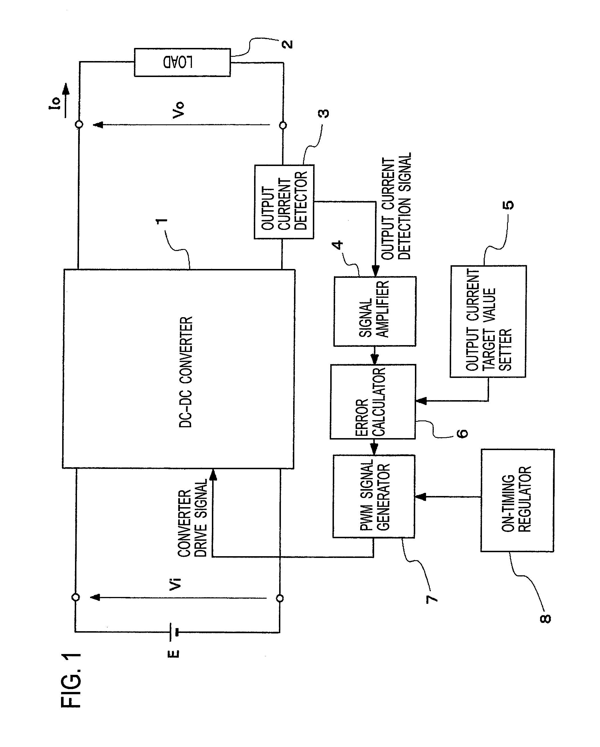
[0067]A circuit diagram of Embodiment 3 of the present invention is illustrated in FIG. 5. This embodiment is different from the above-described embodiments in being composed by providing, as means for regulating the timing of turning on the switching element Q1, a drive frequency setter 81 that sets a frequency of driving the switching element Q1 in place of the ON-timing regulator 8 of Embodiment 1.

[0068]To the drive frequency setter 81, there are inputted: an input voltage detection signal; an output voltage detection signal; and the target current value to be given from the output current target value setter 5. Based on these signals and value, the drive frequency setter 81 sets the drive frequency of the converter drive signal. The set drive frequency is given as a reference oscillation signal to the PWM signal generator 7. Based on the reference oscillation signal thus given, the PWM signal generator 7 creates the converter drive signal that regulates the timing of turning on ...


PUM


Abstract

Provided is a power supply device, which is capable of coping with semiconductor light source loads to be set in various ways, and has high efficiency, in which a current to be supplied to each of the loads has a small ripple. The power supply device supplies power to a semiconductor light source load and lights the semiconductor light source load, and includes: a DC-DC converter; and a controller. The DC-DC converter includes an inductance element and a switching element, and performs voltage conversion by storing energy in the inductance element from an input power source when the switching element is on, and discharging the energy, the energy being stored in the inductance element, to a load side when the switching element is off. The controller controls ON / OFF operations of the switching element so that an output current of the DC-DC converter can be the same as a target value. In the power supply device, means for regulating timing of turning on the switching element so that a current flowing through the inductance element can flow in a continuous mode operation is provided at least in the controller.

Description

TECHNICAL FIELD[0001]The present invention relates to a power supply device using a DC-DC converter, and particularly, relates to a power supply device that supplies power to a semiconductor light source as a load, which is composed of a semiconductor light-emitting element such as a light-emitting diode (LED). Moreover, the present invention relates to a lamp fitting for a headlamp and the like, which uses the power supply device, and to a vehicle including the lamp fitting.BACKGROUND ART[0002]In recent years, a power supply device and a lamp fitting have been actively developed, which use, as a light source, a semiconductor light-emitting element such as a light-emitting diode (LED) in place of a halogen lamp and a discharge lamp. As performance such as light emission efficiency of the LED has been enhanced, these types of the power supply device and the lamp fitting have been expanded to be used not only for a room lamp and a rear combination lamp for a vehicle but also for a hea...

Claims


Application Information

Patent Timeline
Patent Type & Authority Applications(United States)
IPC IPC(8): B60Q1/02H05B37/02H02M3/28H05B44/00
CPCH05B33/0815H02M3/33507H05B45/385
Inventor KANBARA, TAKASHI
Owner PANASONIC CORP
Why Eureka
Try Eureka