Adaptive Switch Mode LED Driver

a technology of led driver and adapter switch, which is applied in the direction of process and machine control, test/measurement of semiconductor/solid-state devices, instruments, etc., can solve the problems of low overall efficiency, low power efficiency of current mirror approach, and prohibitiveness, and achieve fast dynamic response

Active Publication Date: 2011-03-17
DIALOG SEMICONDUCTOR INC
View PDF9 Cites 232 Cited by
  • Summary
  • Abstract
  • Description
  • Claims
  • Application Information

AI Technical Summary

Benefits of technology

[0016]In one embodiment, the luminance controller generates the duty cycle signal for driving the LED strings using a luminance transfer function such that brightness output can be precisely matched between LED strings configured with the same brightness input settings. Additionally the luminance transfer function can include a temperature compensation component to compensate for temperature variations between LED channels.
[0017]Embodiments of the present invention also include a sample and hold current regulator for regulating currents in the LED strings. The sample and hold regulator samples the gate voltage of the regulator pass transistor prior to the channel switch turning off and holds the voltage until the channel switch turns back on. The sample and hold regulator beneficially allows PWM control over extreme duty cycles with very fast dynamic response.

Problems solved by technology

When these power losses are extended over many LED channels, they can become prohibitive.
However, this current mirror approach suffers from low power efficiency.
Since the power dissipated by the current mirrors does not contribute to lighting, the overall efficiency is low, especially when the difference in the combined forward voltage between the LED strings is large.
However, this approach requires fast dynamic response from the LED driver, and thus forces the power converter to operate in deep discontinuous mode (DCM), under which power conversion efficiency is low.
However, this approach results in a wide variation of LED currents between LED strings and leads to LED component stress and reliability control issues.
Additionally, this conventional solution does not provide any native power supply rejection to the boost controller ripple, and thus complicates ADC and digital signal processing requirements.

Method used


Image

  • Adaptive Switch Mode LED Driver
  • Adaptive Switch Mode LED Driver
  • Adaptive Switch Mode LED Driver

Examples


first embodiment

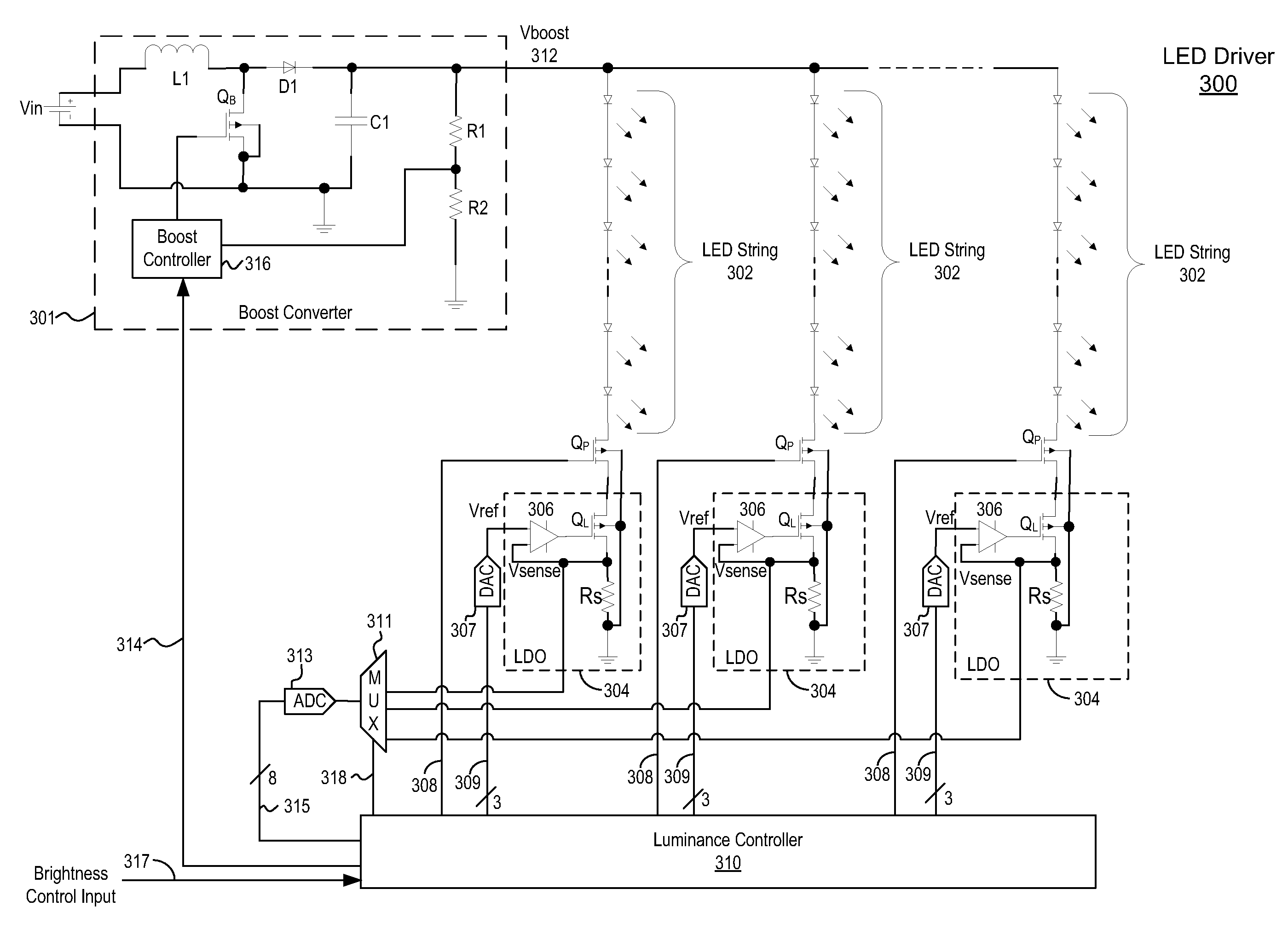
[0035]FIG. 3 is a circuit diagram of an adaptive switch mode LED driver 300. The embodiment comprises boost converter 301 driving one or more parallel LED channels. In each LED channel, LED string 302 is coupled in series with an LDO 304 for regulating current through LED string 302. LED string 302 and LDO 304 are also both coupled in series with PWM switch QP (e.g., an NMOS transistor) for controlling the on-times and off-times of the LEDs in LED string 302. Luminance controller 310 controls the luminance output of each LED channel independently by controlling PWM switches QP via control signals 308, and by controlling LDOs 304 via control signals 309 and digital-to-analog converters (DACs) 307. The LDOs 304 output feedback control signal 315 to luminous controller 310 via multiplexer 311 and ADC 313. Luminance controller 310 also outputs control signal 314 to boost converter 301 for controlling Vboost voltage 312. Although FIG. 3 illustrates only three LED channels, LED driver 300...

second embodiment

[0055]FIG. 5 illustrates an adaptive switch mode LED driver 500. LED driver 500 is similar to LED driver 300 of FIG. 3 described above, but includes a modified LDO 504 and lacks ADC 313. LDO 504 includes op-amp 306, pass transistor QL, and sense resistor RS in an LDO configuration similar to that of LDO 304 described above. However, LDO 504 additionally includes a comparator 506 that compares the output 551 of op-amp 306 to a reference voltage 553 and outputs the resulting signal to the multiplexer 311. In other alternative embodiments, input 551 to comparator 506 can be coupled to the drain or source of LDO transistor QL instead of to the output of op-amp 306.

[0056]In the embodiment of FIG. 5, luminance controller 310 applies a modified calibration process to determine the programmed current In and duty cycle PWM_outn for each LED channel. During the calibration stage, DACs 307 are all initialized to their lowest level. Vboost is then incrementally increased by control signal 314 u...


PUM


Abstract

An adaptive switch mode LED driver provides an intelligent approach to driving multiple strings of LEDs. The LED driver determines an optimal current level for each LED channel from a limited set of allowed currents. The LDO driver then determines a PWM duty cycle for driving the LEDs in each LED channel to provide precise brightness control over the LED channels. Beneficially, the LED driver minimizes the power dissipation in the LDO circuits driving each LED string, while also ensuring that the currents in each LED string are maintained within a limited range. A sample and hold LDO allows PWM control over extreme duty cycles with very fast dynamic response. Furthermore, fault protection circuitry ensures fault-free startup and operation of the LED driver.

Description

BACKGROUND OF THE INVENTION[0001]1. Field of the Invention[0002]The present invention relates to an LED (light-emitting diode) driver and, more specifically, to an LED driver controller that supports multiple strings of LEDs.[0003]2. Description of the Related Arts[0004]LEDs are being adopted in a wide variety of electronics applications, for example, architectural lighting, automotive head and tail lights, backlights for liquid crystal display devices including personal computers and high definition TVs, flashlights, etc. Compared to conventional lighting sources such as incandescent lamps and fluorescent lamps, LEDs have significant advantages, including high efficiency, good directionality, color stability, high reliability, long life time, small size, and environmental safety.[0005]LEDs are current-driven devices, and thus regulating the current through the LEDs is an important control technique. To drive a large array of LEDs from a direct current (DC) voltage source, DC-DC swi...

Claims


Application Information

Patent Timeline
Patent Type & Authority Applications(United States)
IPC IPC(8): H05B37/00H01L21/66H05B44/00
CPCH05B33/0818Y02B20/341H01L22/14H05B33/0842H01L2924/0002H05B33/0827H05B33/0881H01L2924/00H05B45/46H05B45/38Y02B20/30H05B45/325H05B45/395
Inventor JIN, XUECHENGCHANG, YU CHENGLI, YANGLAN, MAOFENGKESTERSON, JOHN W.WANG, XIAOYANPAN, CHENGHUNG
Owner DIALOG SEMICONDUCTOR INC
Why Eureka
Try Eureka