Controller of motor

a controller and motor technology, applied in the direction of electric controllers, motor/generator/converter stoppers, dynamo-electric converter control, etc., can solve the problems of large conduction loss, large switching loss of high-withstand-voltage switching elements, and occupying a significant part of power conversion devices, etc., to achieve low cost, small size, and light weight

Active Publication Date: 2011-03-17
NEXGEN CONTROL SYST LLC
View PDF2 Cites 42 Cited by
  • Summary
  • Abstract
  • Description
  • Claims
  • Application Information

AI Technical Summary

Benefits of technology

According to the controller of a motor of the present invention, a torque generated by an alternating-current motor driven by an inverter is adjusted not to increase an inverter loss, and is generated based on a current command. Therefore, a power conversion device that drives an alternating-current motor can be configured in a small size, light weight, and at a low cost.

Problems solved by technology

However, the high-withstand-voltage switching element has a large switching loss and a large conduction loss.
Accordingly, the magnitude, weight, and cost of a cooler constituted by a radiator and a cooling fan to cool down the loss occupy a significant part of the power conversion device.
When the motor is driven in this state, a pulse number and a pulse position included in a positive half cycle and a negative half cycle, respectively of the inverter output voltage, become unbalanced.
Consequently, positive-and-negative symmetry of the voltage applied to the motor is collapsed, and current oscillation and torque pulsation are generated in the motor, and they become a cause of noise and vibration.

Method used


Image

  • Controller of motor
  • Controller of motor
  • Controller of motor

Examples


Embodiment Construction

Exemplary embodiments of a controller of a motor according to the present invention will be explained below in detail with reference to the accompanying drawings. The present invention is not limited to the embodiments.

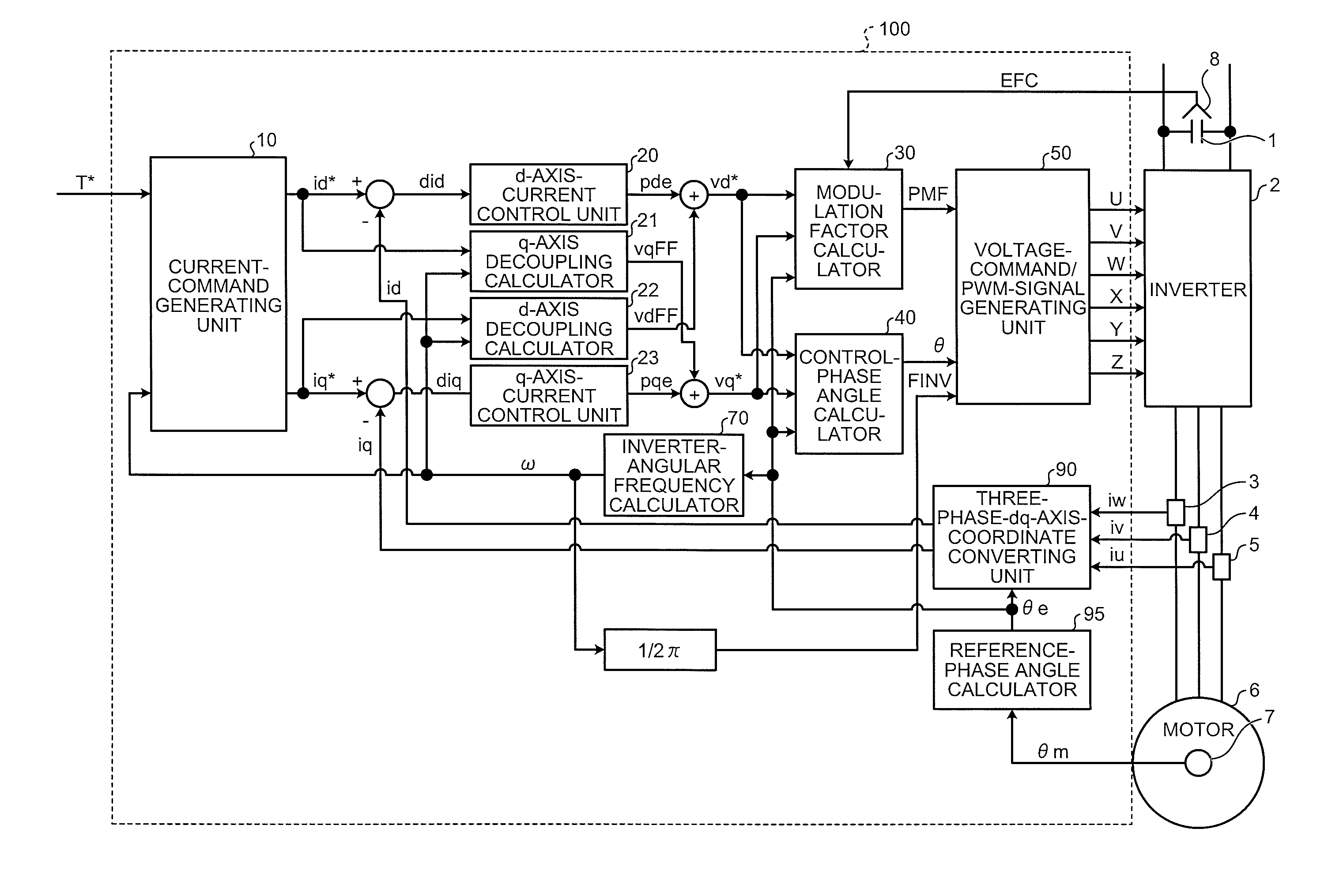
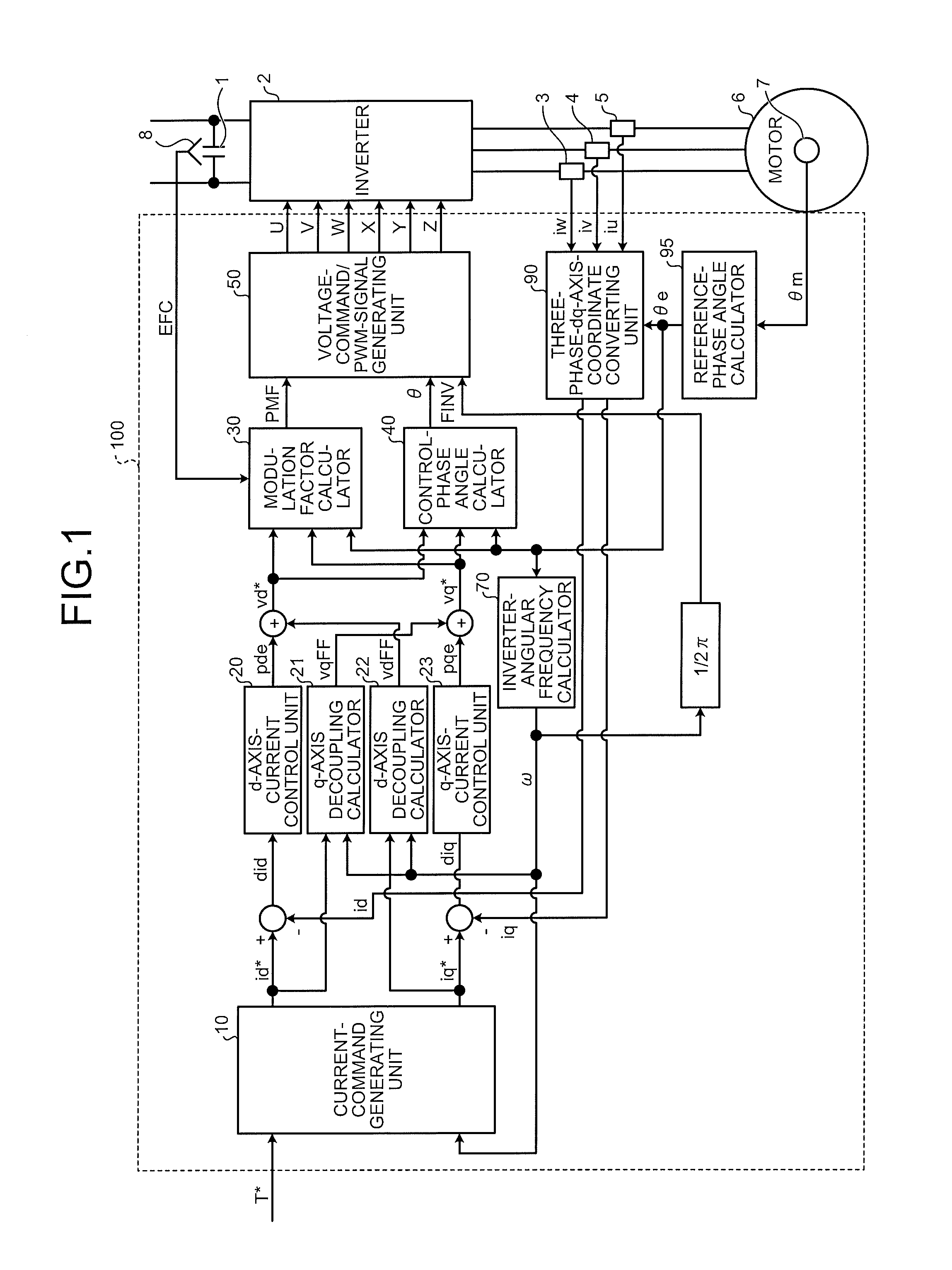
FIG. 1 is a configuration example of a controller of a motor according to an exemplary embodiment of the present invention. As illustrated in FIG. 1, at a peripheral part of a controller 100 of a motor, there are provided a capacitor 1 that becomes a direct-current power source, an inverter 2 that converts a direct-current voltage of the capacitor 1 to an alternating-current voltage of an arbitrary frequency, and a permanent-magnet synchronous motor (hereinafter, simply “motor”) 6.

At a peripheral circuit part positioned at an input side or an output side of the inverter 2, there are arranged a voltage detector 8 that detects a voltage of the capacitor 1, and current detectors 3, 4, and 5 detecting currents iu, iv, and iw of output lines of the inverter 2. A resolver 7...


PUM


Abstract

In configuring a power conversion device to drive an alternating-current motor for an electric vehicle, the device is configured in a small size, light weight, and at a low cost, while avoiding size increase of a cooler. A current-command generating unit provided in a controller to control the alternating-current motor is adjusted not to increase a loss of an inverter in a state that the inverter as a main circuit within the power conversion device is outputting a maximum voltage that can be generated at an output voltage of a direct-current power source and when a torque command is reduced, and outputs a current command to cause the alternating-current motor to generate a torque based on the torque command.

Description

TECHNICAL FIELDThe present invention relates to an alternating-current motor to drive an electric vehicle, and, more particularly to a controller of a motor suitable to control a permanent-magnet synchronous motor.BACKGROUND ARTRecently, in the technical field of alternating-current-motor such as industrial devices, household appliances, and cars, there are increasing cases of using a system that drives a permanent-magnet synchronous motor by an inverter, in place of a conventional system that drives an induction motor by an inverter.The permanent-magnet synchronous motor is known as a highly efficient motor as compared with the induction motor for the following reasons: because a magnetic flux of a permanent magnet is established, an excitation current is not necessary; because no current flows to a rotor, a secondary copper loss does not occur; and because a reluctance torque using a difference of magnetic resistance of a rotor is used in addition to a torque generated by a magnet...

Claims


Application Information

Patent Timeline
Patent Type & Authority Applications(United States)
IPC IPC(8): H02H7/09
CPCH02P27/08H02P21/0035H02P21/22
Inventor KITANAKA, HIDETOSHI
Owner NEXGEN CONTROL SYST LLC
Why Eureka
Try Eureka