
Cantilever with paddle for operation in dual-frequency mode

Inactive Publication Date: 2011-03-17
KERNFORSCHUNGSZENTRUM KARLSRUHE GMBH +1
View PDF2 Cites 6 Cited by
  • Summary
  • Abstract
  • Description
  • Claims
  • Application Information

AI Technical Summary

Benefits of technology

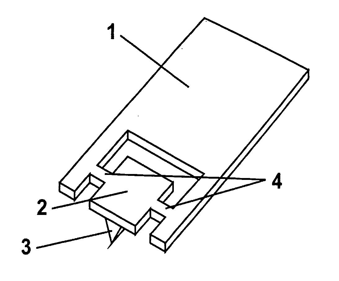
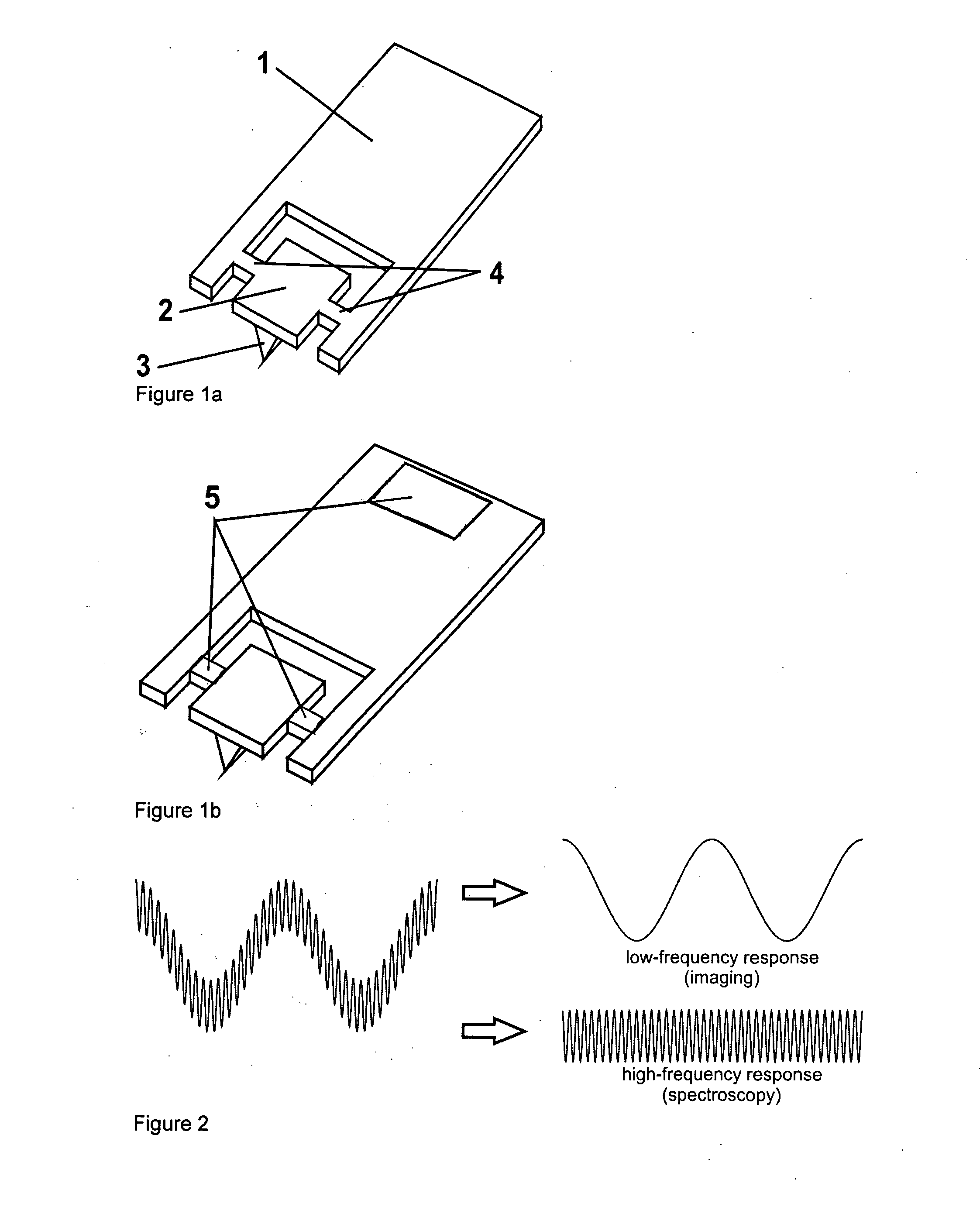
[0015]The design according to the instant invention ensures that the oscillation of the cantilever, which is used to acquire the sample topography, is nearly completely decoupled from the oscillation of the paddle, which is used to detect the tip-sample interactions.
[0016]The oscillation of the paddle is brought about

Problems solved by technology

However, these additional measurements can only be performed through a subsequent characterization after scanning of the surface topography.
The conventional techniques that are already established do not allow the simultaneous analysis of the tip-sample interactions during imaging of the surface.
However this is quite complex to perform and the noise is high.
However these have the disadvantage of a coupling between the lateral and normal motion of the cantilever.

Method used


Image

  • Cantilever with paddle for operation in dual-frequency mode
  • Cantilever with paddle for operation in dual-frequency mode

Examples


Embodiment Construction

[0012]In the instant invention the terms “cantilever”, “cantilever system”, “microcantilever” and “microcantilever system” are used synonymously.

[0013]Through modification of a standard AFM cantilever with a FIB (focused ion beam) or through direct micromachining, the instant invention's cantilevers that have a paddle attached at the free end were made (sometimes referred to as “paddle cantilevers” in the following).

[0014]The paddles of the instant invention's cantilevers can be designed to oscillate at frequencies that are significantly higher (1-1000 MHz) than the fundamental frequency of the cantilever (a few tens of kHz). In the context of the instant invention it was found that through proper design it is possible to select the force constant, oscillation amplitude (given a set of AFM operation parameters) and frequency of the paddle, such that a good signal-to-noise relation can be achieved.

[0015]The design according to the instant invention ensures that the oscillation of the...


PUM


Abstract

A microcantilever system comprising a paddle, its use and a method of simultaneously acquiring the topography and measuring the tip-sample interactions of a sample with it.

Description

[0001]This application claims priority to U.S. provisional application 61 / 096,943 filed on Sep. 15, 2008.[0002]The entire disclosure of the prior application is considered to be part of the disclosure of the instant application and is hereby incorporated by reference.[0003]Any of the documents cited herein are incorporated by reference in their entirety.[0004]The instant invention concerns specific microcantilevers and their use in atomic force microscopy.BACKGROUND OF THE INVENTION[0005]The atomic force microscope (AFM) has become a standard instrument in nano-analysis with regards to the rapid and uncomplicated technical exploration of surfaces at the micro- and nanometre scales. During characterization, a probe mounted at the end of a cantilever beam is generally placed in direct contact with the sample, such that the surface topography is obtained through a raster scan while maintaining a constant tip-sample force. An important upgrade to this basic process is the so-called dyna...

Claims


Application Information

Patent Timeline
IPC IPC(8): G01Q60/24
CPCB82Y35/00G01Q70/10G01Q60/38G01Q60/32
Inventor HOLSCHER, HENDRIKSOLARES, SANTIAGO DE JESUS
Owner KERNFORSCHUNGSZENTRUM KARLSRUHE GMBH
Learn More