
Architectural pavements in elevated exterior deck applications

Inactive Publication Date: 2011-03-24
CASATA TECH
View PDF26 Cites 57 Cited by
  • Summary
  • Abstract
  • Description
  • Claims
  • Application Information

AI Technical Summary

Benefits of technology

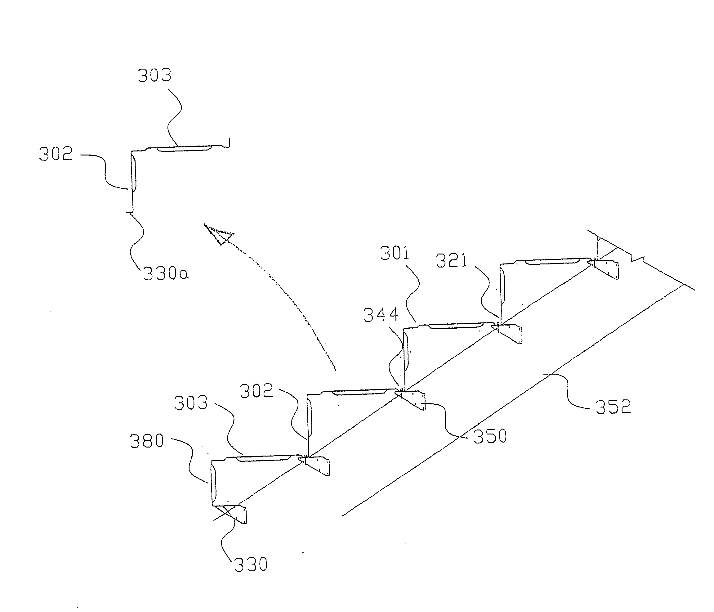
[0012]At the intersection of the deck portion and web portion, the deck portion preferably is jogged inwardly to provide an offset shelf section running longitudinally along the length of the joist. The shelf section is set below the upper surface of the deck portion to provide support for the distal edge of the deck portion of an adjacent joist. The distal edge of the deck portion is also jogged inwardly to provide an offset shelf section running longitudinally along the length of the joist. The offsets are relatively dimensioned such that when a tail of one joist is supported on the shelf section of an adjacent joist, the deck portions lie in a common plane. These continuous longitudinal offsets are recessed into the plane of the deck portion to allow for nesting and fastening while maintaining a singe horizontal datum surface on which to apply stone pavers, tiles, or the like on a common datum surface and minimize rocking, splitting or cracking of stones or pavers due to an uneven surface or the projection of the fastener heads above the datum surface. In a nested configuration, the continuous longitudinal offsets provide increased sectional rigidity which contributes to limit vertical deflections and resist crippling under loading conditions, and achieves a structural efficiency that is not achievable with a single piece structural element of similar thickness. The next joist is then positioned with its tail resting on the shelf section of the preceding joist. The wider shelf section allows the tail to be adjusted along the length of the joist to maintain the required alignment between the joists and provides for flexibility of alignment and pitch during assembly of the joists to accommodate variability and dimensional inaccuracies of structures in an as-built condition. Normally, such an alignment is parallel to one another, but in some circumstances the joists may be fanned relative to each other to provide an arcuate surface in plan. With the joists positioned, fasteners are inserted through the tail and shelf section, and fasteners inserted through the flange in to the supporting beam.
[0013]The deck assembly may optionally comprise lower chord bridging to span an open area beneath the platform portion of the joist to provide increased structural rigidity, and prevent the platform from tortionally deforming.
[0015]Preferably, the joists of the deck assembly are manufactured from a metal or a metal alloy, such as flat rolled steel with a galvanized or organic coatings to prevent corrosion. Alternatively, the joists may be manufactured from prepainted steel, a composite material, or a plastics material, depending on the intended use and loading conditions. The joists of the deck are preferably manufactured using light gage galvanized steel in thickness of between 1 mm and 3 mm with 1.42 mm to 2 mm preferred, to provide a lightweight structure for ease of assembly of a deck and satisfying structural performance conditions required by applicable building regulations.

Problems solved by technology

One of the major drawbacks of modern joist systems is that they require substantial time to erect.

Method used


Image

  • Architectural pavements in elevated exterior deck applications
  • Architectural pavements in elevated exterior deck applications
  • Architectural pavements in elevated exterior deck applications

Examples


Embodiment Construction

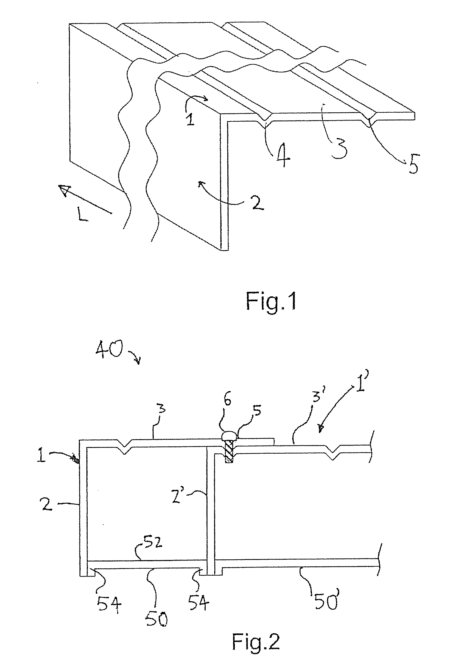
[0046]Referring to FIG. 1, a joist 1 for use in a deck assembly 40 comprises a web portion 2 and a deck portion 3. It will be appreciated that the joists are of indeterminate length L and may be customized to the length required. The deck portion 3 extends outwardly from the web portion 2 and the included angle between the deck portion 3 and web portion 2 is typically 90°, although other angles may be incorporated. The deck portion 3 is provided with a pair of V-shaped recesses 4, 5 at spaced locations that are proximal to and distal from the web portion 2 respectively. The joist 1 is formed from a rolled steel strip of appropriate gauge and the joists 1 may be pre-finished by painting, powder coating or galvanising to inhibit corrosion.

[0047]A plurality of joists 1, 1′ of FIG. 1 are assembled as shown in FIG. 2 to form a deck assembly 40. The web portions 2, 2′ of each joist are aligned vertically in parallel with the deck portions 2, 2′ overlapping. The distal V-shaped recess 5 en...


PUM


Abstract

A deck assembly uses plurality of joists preferably formed from metal located side by side and each having a web portion and a deck portion integrally formed with the web portion. The deck portion extends laterally from the web portion and the joists are spaced from one another such that the deck portions from a continuous deck surface with the joists being connected to one another.

Description

CROSS-REFERENCE TO RELATED APPLICATIONS[0001]This application is a continuation in part of U.S. application Ser. No. 12 / 270,645 filed on Nov. 13, 2008 which is a continuation in part of PCT / CA2007 / 001142 filed on Jun. 26, 2007 which claims priority from U.S. Provisional Application No. 60 / 816,348 filed on Jun. 26, 2006 both incorporated herein by reference. This application also claims priority from U.S. Provisional Application No. 60 / 987,528 filed on Nov. 13, 2007, hereby incorporated by reference.FIELD OF THE INVENTION[0002]The present invention relates to an integrated platform joist, an integrated platform joist system, and a method for assembling such a system.DESCRIPTION OF THE PRIOR ART[0003]Joist systems are used in the construction industry to span a distance between opposing walls and provide a structural support for a floor, a roof or other platform. The joists are individual units spaced apart and support a decking that forms a sub-floor. Such joists can be manufactured ...

Claims


Application Information

Patent Timeline
IPC IPC(8): E04C3/02E04C3/00E04F11/02
CPCE04C2003/046E04F11/00E04F11/025E04C3/02E04F15/06E04B1/18E04F11/112E04B5/10E04B2103/06E04C3/07E04C3/04E04C3/09
Inventor NACCARATO, JOHN R.SEVERINI, JOSEPH A.
Owner CASATA TECH
Learn More