
Solder preform and a process for its manufacture

a technology of preform and solder, which is applied in the direction of manufacturing tools, solventing apparatus, transportation and packaging, etc., can solve the problems of voids and vaporization of flux, and achieve the effect of demonstrating the bonding strength of solder

Active Publication Date: 2011-03-24
SENJU METAL IND CO LTD +1
View PDF12 Cites 16 Cited by
  • Summary
  • Abstract
  • Description
  • Claims
  • Application Information

AI Technical Summary

Benefits of technology

[0025]Namely, when flux is mixed with metal particles, solids in the flux such as rosin, an activator, and a thixotropic agent are dissolved in a solvent. When the flux is charged into molten solder, a large portion of the solvent vaporizes, and the solids remain as flux. Flux remaining in a solder preform is a solid at room temperature, but when the remaining flux is heated at the time of soldering, it is liquified and then vaporized. When flux undergoes a phase change from a liquid to a gas, its volume increases by several thousand times, and even a minute amount of flux forms large voids. Therefore, as described above, with a solder preform in which a minute amount of flux remains, the bonding area decreases, thereby decreasing the bonding strength and heat dissipation capacity and causing parts to tilt. In addition, when a solder preform is melted, flux remaining in the solder preform oozes out from the solder and adheres to the periphery of soldered portions and has an effect on the curing of resins used for resin molding or potting.
[0027]The present inventors found that if stirring is performed a plurality of times for a short period after metal particles are charged into molten solder, flux adhering to the metal particles can be entirely removed and metal particles are no longer eroded by molten solder. In addition, if components which are easily decomposed by the heat of molten solder are used to form a flux which is mixed with metal particles, the flux will no longer remain in a solder preform.
[0028]The present inventors also found that if metal particles are directly charged into molten solder, a long time is required for uniform dispersion of metal particles, and erosion of metal particles progresses. Such problems can be solved by previously mixing metal particles and a small amount of molten solder to prepare a mixed mother alloy and charging the mixed mother alloy into molten solder. The flux remaining at the time of preparation of the mixed mother alloy can also be completely eliminated when subsequently charging the mixed mother alloy into molten solder.
[0038]In a process for manufacturing a solder preform according to the present invention, a mixture of flux and metal particles is charged into molten solder and then stirred and rapidly cooled when preparing a mixed mother alloy, and the mixed mother alloy is then charged into molten solder and again stirred and rapidly cooled when preparing a billet. Therefore, a stirring operation is carried out two times, and flux adhering to metal particles is thereby completely removed. In addition, flux used in a manufacturing process according to the present invention easily undergoes pyrolysis (thermal decomposition). Therefore, when the mixture is charged into molten solder or when the mixed mother alloy is charged into molten solder, the flux completely decomposes and does not remain in solder. Accordingly, when carrying out soldering of parts with a solder preform obtained by the manufacturing process according to the present invention, not only is there substantially no occurrence of voids, but there also is no oozing of flux to the periphery of soldered portions.
[0039]As a solder preform according to the present invention has metal particles uniformly dispersed therein, when parts are soldered, a constant clearance is obtained between the portions being soldered of the parts, and substantially no voids are present in the solder preform. Therefore, the inherent bonding strength of solder can be exhibited.
[0040]In addition, because a solder preform according to the present invention does not have oozing of flux to the periphery of soldered portions, the curing of resin is not impeded even if resin molding or potting is carried out after soldering. As a result, soldered portions of excellent reliability are obtained.

Problems solved by technology

As a result of diligent investigation of the cause of the occurrence of voids and oozing of flux to the periphery of soldered portions with a solder preform obtained by the conventional melting method, they found that there is a problem with flux used when manufacturing solder preforms and with a process for manufacturing solder preforms.
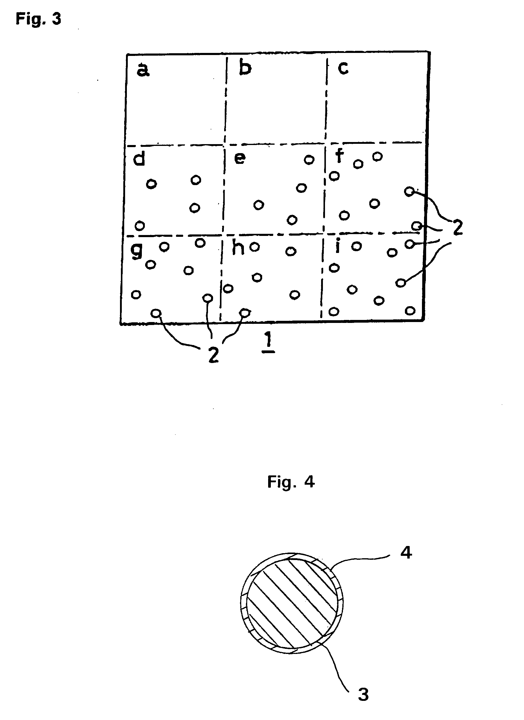
If even a minute amount of flux remains in a solder preform, even though the flux itself does not become voids, when such a solder preform is sandwiched between the portions to be soldered of parts and heated, the flux vaporizes and produces voids.

Method used

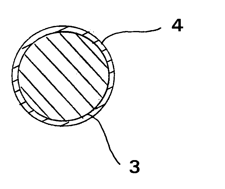

Image

  • Solder preform and a process for its manufacture
  • Solder preform and a process for its manufacture
  • Solder preform and a process for its manufacture

Examples


example 1

[0082]Solder preforms were prepared by the following steps (1)-(6).

[0083](1) Ni particles with a diameter of 50 μm were washed with dilute hydrochloric acid to clean their surfaces, and 4.5 grams of the Ni particles which had their surfaces cleaned were mixed with 0.45 grams of a pyrolyzable liquid flux having the following composition to obtain a mixture.

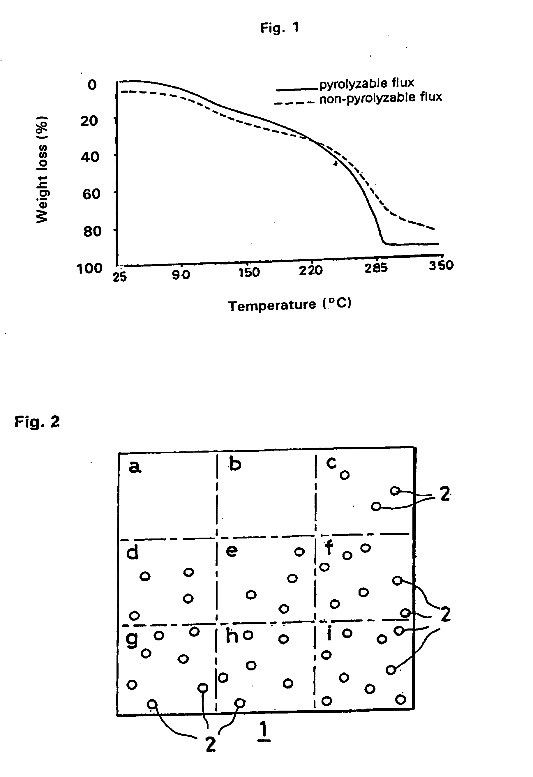
[0084]The composition of the liquid flux used at this time was as follows. Its weight loss at 285° C. was 80% on a heating weight loss curve obtained by TG.

[0085]60.0 mass percent of rosin (hydrogenated rosin),

[0086]10.0 mass percent of activator (diethylaniline HBr), and

[0087]30.0 mass percent of solvent (ethylene glycol monoethyl ether).

[0088](2) The mixture was charged into 125 g of a Sn—Cu—Ni—P based lead-free solder (melting point of approximately 230° C.) comprising 99 mass percent of Sn and a remainder of Cu, Ni, and a minute amount of P which had been melted at approximately 285° C. in a cast iron ladle, and the molten sold...

example 2

[0093]Solder preforms were prepared by the following steps (1)-(6).

[0094](1) Ni particles with a diameter of 50 μm were washed with dilute hydrochloric acid to clean their surfaces, and 4.5 g of the Ni particles with cleaned surfaces were mixed with 0.45 g of a pyrolyzable liquid flux having the following composition to obtain a mixture.

[0095]The flux composition used in this example was as follows. Its weight loss at 285° C. was 80% on a heating weight loss curve obtained by TG.

[0096]60.0 mass percent of rosin (hydrogenated rosin),

[0097]10.0 mass percent of activator (diethylaniline HBr), and

[0098]30.0 mass percent of solvent (ethylene glycol monoethyl ether).

[0099](2) The mixture was charged into 125 g of a Sn—Ag—Cu based lead-free solder (melting point of approximately 220° C.) which had been melted at 285° C. in a crucible, and after stirring was performed for approximately 20 seconds with a metal spatula, the crucible was left in a vacuum apparatus for approximately 3 minutes t...


PUM

PropertyMeasurementUnit
thicknessaaaaaaaaaa
particle diameteraaaaaaaaaa
thicknessaaaaaaaaaa

Abstract

A mixed mother alloy is prepared from a solder mixture comprising a pyrolyzable flux and high melting point metal particles, the mixed mother alloy is charged into a large amount of molten solder and stirred, and a billet is prepared. The billet can then be extruded, rolled, and punched to form a pellet or a washer, for example.

Description

REFERENCE TO RELATED APPLICATIONS[0001]This application is a continuation-in-part of application Ser. No. 12 / 073,690 filed on Mar. 7, 2008, now U.S. Pat. No. 7,793,820, which is a continuation-in-part of International Application Ser. No. PCT / JP2006 / 318248 having an international filing date of Sep. 14, 2006.BACKGROUND OF THE INVENTION[0002]This invention relates to a solder preform having high melting point metal particles uniformly dispersed therein and a process for its manufacture.[0003]A typical soldering method for constituent parts such as printed circuit boards and electronic parts used in electronic equipment (referred to below as electronic parts or simply as parts) is the reflow soldering method.[0004]The reflow soldering method is a method in which solder is placed only on necessary locations of a part, and then heating is performed by a heating apparatus such as a reflow furnace, an infrared irradiating apparatus, or a laser irradiating apparatus to carry out soldering....

Claims


Application Information

Patent Timeline
Patent Type & Authority Applications(United States)
IPC IPC(8): B23K35/14B22F1/17
CPCB22F1/025B23K35/0244C22C13/00B23K35/3033B23K35/36B23K35/262B22F1/17
Inventor HIRANO, NAOHIKOTANAHASHI, AKIRASAKAMOTO, YOSHITSUGUTSURUTA, KAICHIISHII, TAKASHISOGA, SATOSHI
Owner SENJU METAL IND CO LTD
Learn More