Method of Tuning Bending and Torsion Stiffness of Ducted Rotor Core of An Induction Motor

a technology of induction motor and rotor core, which is applied in the direction of static/dynamic balance measurement, magnetic circuit shape/form/construction, instruments, etc., can solve the problems of increasing the critical vibration frequency of the motor, reducing the variance of individual rotordynamic characteristics, and reducing the risk of rotor flexing and flexing

Active Publication Date: 2011-03-31
INNOMOTICS LLC
View PDF18 Cites 38 Cited by
  • Summary
  • Abstract
  • Description
  • Claims
  • Application Information

AI Technical Summary

Benefits of technology

[0012]Another object of the present invention is to alter induction motor rotordynamic stability by selectively tuning the entire rotor structure stiffness, so that the motor critical vibration speed can be altered.
[0013]An additional object of the present invention is to tune induction motor rotor stiffness in a virtual environment. In the virtual environment the designer having the ability to alter the rotor physical design, test intended applications of the motor design under different operational parameters that impact rotordynamic stability, and provide for a range of physical characteristics of the rotor stiffness that may result from predictable manufacturing variations in component tolerances and manufacturing processes. In this manner the ultimate critical frequency of the induction motor in the intended application becomes more predictable to the motor designer, applications engineer or customer.
[0014]It follows that another object of the present invention is to reduce potential manufacturing variations in induction motor rotors through use of the tuning methods and apparatus described herein, and thereby better predict the critical vibration speed of the induction motor after its manufacture.
[0022]Tuning rotor stiffness by varying the rotor tie rod array and compression forces on the rotor stack allows a motor designer to predict the resultant impact on the motor's critical vibration speed. Tuning can take into account consequences of design applications, such as for example how varying motor excitation frequency with a motor drive controller impacts motor vibration. Tuning concepts of the present invention also reduce variances in individual rotordynamic characteristics by more consistent rotor fabrication. Insertion of a tie rod array into the rotor laminas stack prior to press fitting the shaft facilitates more consistent rotor fabrication. Vibration variances after manufacture can be compensated after assembly by selectively varying the tie rod array and compression. The motor tuning apparatus and methods of the present invention also facilitate cooler motor operation. By incorporating a relatively smaller motor shaft diameter while otherwise achieving desired rotor stiffness additional rotor cross-sectional area can be allocated to enlarge axial cooling passages.

Problems solved by technology

Generally oil lubricated hydrodynamic bearings in induction motors are susceptible to oil whip when the rotor speed is over roughly twice bearing system's inherent critical speed.
Oil whip vibration instability causes the rotor shaft to flex in a sinusoidal curve between the bearings.
Thus, increasing the rotor shaft stiffness raises the motor's critical vibration frequency.
There are motor design performance tradeoffs associated with increasing rotor shaft diameter.
Conversely, reducing shaft diameter may enable a designer to improve motor cooling but risks increasing shaft flexure and lowering the motor critical vibration speed.
It should also be noted that an optimal motor shaft diameter for one motor frame design in a 60 Hz alternating current system application may not be optimal for a 50 Hz AC application.
Despite efforts to raise induction motor critical vibration speed through rotor stiffness and other design optimization, potential manufacturing variations alter critical vibration speed for any given completed physical motor.
Unfortunately, known rotordynamic stability solutions to attempt to raise critical vibration speeds through changes in induction motor design have not provided system-level solutions of how to tune critical vibration characteristics from one motor design to another, from one application of a specific motor design to a different application, or individual manufacturing variances.

Method used


Image

  • Method of Tuning Bending and Torsion Stiffness of Ducted Rotor Core of An Induction Motor
  • Method of Tuning Bending and Torsion Stiffness of Ducted Rotor Core of An Induction Motor
  • Method of Tuning Bending and Torsion Stiffness of Ducted Rotor Core of An Induction Motor

Examples


Embodiment Construction

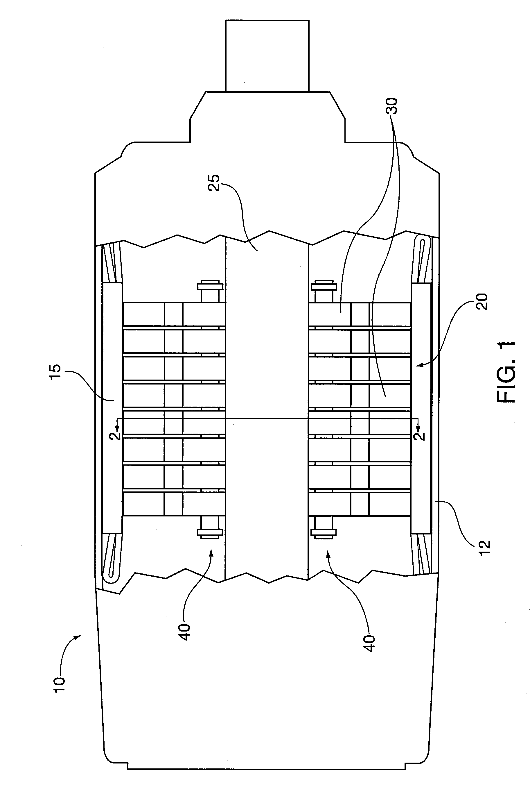
[0030]After considering the following description, those skilled in the art will clearly realize that the teachings of my invention can be readily utilized for tuning rotating mass structural stiffness and vibration excitation frequencies in dynamoelectric machines, and more particularly to methods for tuning rotor stiffness and critical speed vibration in induction motors through the use of axial tie rod arrays.

[0031]Tuning rotor stiffness by varying the rotor tie rod array and compression forces on the rotor stack allows a motor designer to predict the resultant impact on the motor's critical vibration speed caused by the motor physical design and the intended application environment.

[0032]The present invention use of axial tie rod arrays as part of the rotor fabrication process reduces rotor manufacturing variances, potentially leading to more predictable conformity of the finished motor to its vibration specifications.

[0033]FIG. 1 shows an electrodynamic machine induction motor ...


PUM

PropertyMeasurementUnit
frequenciesaaaaaaaaaa
frequencyaaaaaaaaaa

Abstract

Electrodymamic machine rotating mass, including for example induction motor rotors, stiffness tuning methods include selective orientation and compression of modular tie rod assemblies into through bores formed in the rotor lamination core outboard of the rotor shaft during motor manufacture, repair or refurbishment. Stiffness tuning enables a motor manufacturer to tune a rotor's rotordynamic stability, and hence the assembled motor's critical vibration speed. Electrodynamic machine rotating mass tuning can be adjusted in response to machine physical design, operational application and manufacturing variation attributes that impact the assembled machine's critical vibration frequency. Thus the present invention offers a systematic, holistic approach to motor vibration refinement through use of a simple kit of modular tie rod assemblies oriented and tightened in a selected array. Rotor stiffness tuning can be tested virtually on computer work stations. Additional actual rotor stiffness tuning can be performed during manufacture.

Description

BACKGROUND OF THE DISCLOSURE[0001]1. Field of the Invention[0002]The invention relates to methods for tuning rotating mass structural stiffness and vibration excitation frequencies in dynamoelectric machines, and more particularly to methods for tuning rotor stiffness and critical speed vibration in induction motors. The invention enables a motor manufacturer to vary selectively rotor stiffness and the motor's critical vibration speed, preferably so that the critical speed is above the highest planned motor operational speed in a single or variable speed motor application.[0003]2. Description of the Prior Art[0004]Machines with rotating masses, including electrodynamic machines, inherently have critical vibration excitation speeds attributable to the structural mechanics of the device and associated system operational forces. In electromechanical systems it is advisable to avoid operating machinery at its first or subsequent harmonic vibration frequency so as to avoid premature wear...

Claims


Application Information

Patent Timeline
Patent Type & Authority Applications(United States)
IPC IPC(8): H02K1/28H02K15/02
CPCH02K1/22Y10T29/49012H02K7/16H02K7/04
Inventor SINGHAL, SUMIT
Owner INNOMOTICS LLC
Why Eureka
Try Eureka