Current carrying block for resistance welding, and method for manufacturing sealed battery and sealed battery each using the current carrying block

Active Publication Date: 2011-03-31
SANYO ELECTRIC CO LTD
View PDF11 Cites 12 Cited by
  • Summary
  • Abstract
  • Description
  • Claims
  • Application Information

AI Technical Summary

Benefits of technology

[0077]With the sealed battery of the invention, as compared with a conventional sealed battery, the resistance-welded portion between the positive electrode substrate exposed portion or the negative electrode

Problems solved by technology

However, the internal resistance of the battery is required to be reduced as much as possible because a large current flows in the battery when it is discharged at high power.
However, characteristics of the aluminum, aluminum alloy, copper, and copper alloy include a small electric resistance and large thermal conductivity, requiring a very large amount of energy is required for the welding.
Furthermore, the laser welding method presents other issues such as when the aluminum, aluminum alloy, copper, or copper alloy is laser-welded, the weldability greatly varies depending on the surface conditions, and the occurrence of spattering is unavoidable, similar to laser welding of other materials.
In the ultrasonic welding, a large amount of energy is also required because the aluminum, aluminum alloy, copper, and copper alloy that are the metals to be welded have large thermal conductivity, and furthermore, the positive electrode active material and negative electrode active material can possibly fall off due to the ultrasonic vibration during welding.
In addition, the resistance welding presents issues such as a high current is required to be input in a short period because the aluminum, aluminum alloy, copper, and copper alloy as the metals to be welded have a small electric resistance and large thermal conductivity, the electrode rod for resistance welding and the collector member are sometimes melted together during resistance welding, and melting or spark occurs at locations other than the welded part.
Moreover, when a large welding energy is applied during resistance welding, the amount of spattered particles increases thereby increasing the possibility that the particles migrate to the electrode assembly resulting in an internal short circuit.
However, the invention presents an issue in being a complex fabrication apparatus.
Thus, in order to stably weld the sta

Method used


Image

  • Current carrying block for resistance welding, and method for manufacturing sealed battery and sealed battery each using the current carrying block
  • Current carrying block for resistance welding, and method for manufacturing sealed battery and sealed battery each using the current carrying block
  • Current carrying block for resistance welding, and method for manufacturing sealed battery and sealed battery each using the current carrying block

Examples


Example

First Embodiment

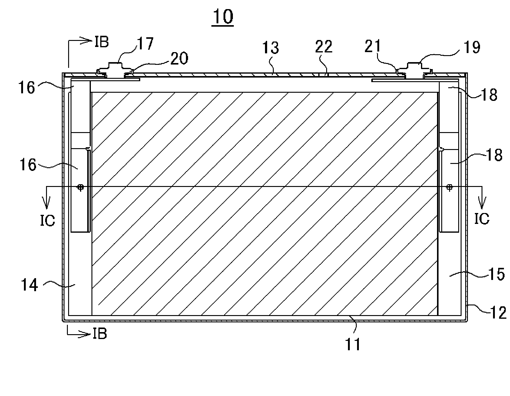
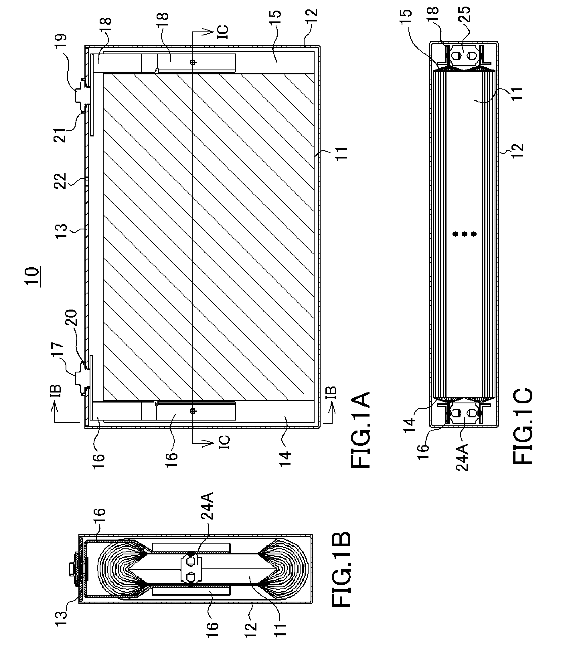
[0090]First, as an example of the sealed battery of a first embodiment of the present invention, a prismatic nonaqueous electrolyte secondary battery will be described with reference to FIGS. 1A to 1C. FIG. 1A is a cross-sectional view showing the nonaqueous electrolyte secondary battery of the first embodiment, FIG. 1B is a cross-sectional view taken along the line IB-IB of FIG. 1A, and FIG. 1C is a cross-sectional view taken along the line IC-IC of FIG. 1A. The nonaqueous electrolyte secondary battery 10 includes a flat wound electrode assembly 11 in which positive and negative electrode sheets (not shown) are wound with a separator interposed therebetween (not shown).

[0091]The positive electrode sheet is prepared by applying a positive electrode active material mixture on both sides of a positive electrode substrate made of aluminum foil so as to form a positive electrode substrate exposed portion 14 where strip-shaped aluminum foil is exposed, drying the resultin...

Example

Second Embodiment

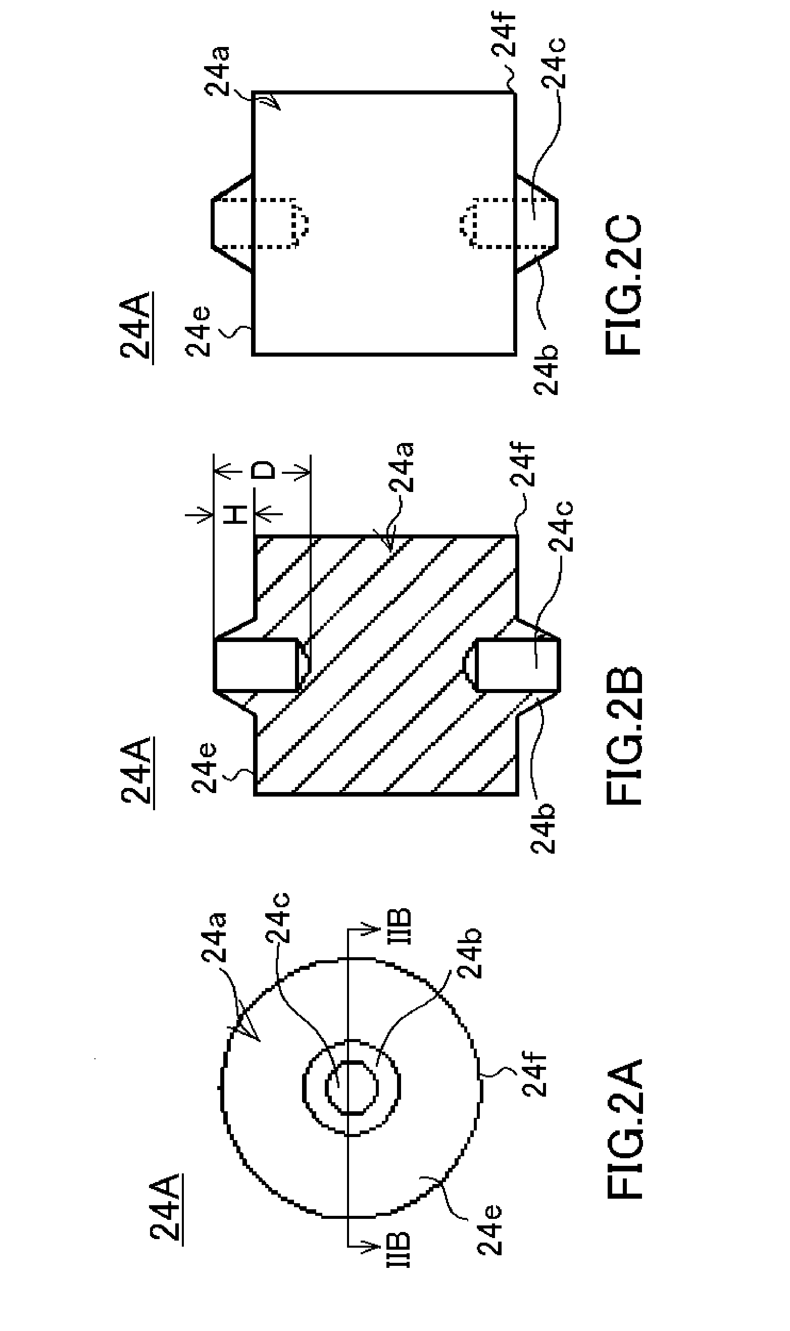
[0114]The first embodiment has exemplified, as shown in FIGS. 2A to 2C, the current carrying block for the positive electrode 24A in which, for example, the truncated-cone-shaped protrusion 24b is formed on each of the two opposing faces 24e of the column-shaped main body 24a. In this manner, when the main body 24a has a column shape, the column-shaped main body 24a has a corner 24f between each of the two opposing faces 24e and the side face. Consequently, as shown in FIG. 3, when the current carrying block for the positive electrode 24A is placed inside the two-divided stacked positive electrode substrate exposed portions 14 so as to bring each of the truncated-cone-shaped protrusions 24b on the current carrying block for the positive electrode 24A into contact with the stacked positive electrode substrate exposed portions 14, the corner 24f readily comes in contact with the stacked positive electrode substrate exposed portion 14, and thus the positive electrode s...

Example

Third Embodiment

[0119]The second embodiment has exemplified the current carrying block for the positive electrode 24B in which the chamfered face 24g is formed at the corner 24f between each of the two opposing faces 24e and the side face of the column-shaped main body 24a in the first embodiment as well as the protrusion 24b has no opening. Furthermore, the first embodiment has exemplified the current carrying block for the positive electrode 24A in which the opening 24c formed in the protrusion 24b has a depth D larger than the height H of the protrusion 24b (see FIG. 2B). However, the depth D of the opening 24c formed in the protrusion 24b may be smaller than the height H of the protrusion 24b. The structure of such a current carrying block for the positive electrode 24D of a third embodiment of the present invention is shown in FIG. 6C. FIG. 6C is an elevation view showing the current carrying block for the positive electrode 24D of the third embodiment.

[0120]With the current ca...


PUM

PropertyMeasurementUnit
Currentaaaaaaaaaa
Pressureaaaaaaaaaa
Currentaaaaaaaaaa

Abstract

In a sealed battery, a metal current carrying block 24A having a protrusion 24b on each of the two opposing faces is placed between positive or negative electrode substrate exposed portions that are divided into two so as to bring the protrusion 24b on each of the two opposing faces into contact with the positive or negative electrode substrate exposed portions that are stacked, a pair of electrodes 31 and 32 for resistance welding are brought into contact with positive electrode collector members 16 or negative electrode collector members that are each placed on the outermost surfaces of the positive electrode substrate exposed portions 14 or negative electrode substrate exposed portions, and resistance welding is performed with pressure applied between the pair of electrodes 31 and 32 for resistance welding.

Description

TECHNICAL FIELD[0001]The present invention relates to a current carrying block for resistance welding by which, in a sealed battery having positive electrode substrate exposed portions and negative electrode substrate exposed portions that are stacked and divided into two, the resistance between respective substrate exposed portions and a collector member can be lowered and each of the substrate exposed portions and the collector member can be stably resistance-welded in a single welding step, and relates to a method for manufacturing a sealed battery and a sealed battery, each using the current carrying block.BACKGROUND ART[0002]Recently, the environmental movement has been active, and the exhaust regulations of exhaust gas such as carbon dioxide gas that causes the global warming are becoming more rigorous. Thus, in the car industry, electric vehicles (EVs) and hybrid electric vehicles (HEVs) have been actively developed in place of automobiles using fossil fuels such as gasoline,...

Claims


Application Information

Patent Timeline
IPC IPC(8): H01M2/00B23K11/24H01M6/00H01M50/528
CPCB23K11/11H01M2/22Y10T29/49108H01M10/0587Y10T29/4911H01M10/05Y02E60/10H01M50/528Y02P70/50
Inventor KIMURA, TAKENORIKAMIFUJI, TAIKIYAMAMOTO, KOUSUKEYOKOYAMA, YOSHINORI
Owner SANYO ELECTRIC CO LTD
Why Eureka
Try Eureka