Bipolar plate for fuel cell and fuel cell

a fuel cell and bipolar plate technology, applied in the direction of fuel cell details, collectors/separators, electrochemical generators, etc., can solve the problems of reducing the output of the fuel cell, affecting the efficiency of water discharge, so as to achieve stable power generation and effective discharge of water

Inactive Publication Date: 2011-03-31
HITACHI LTD
View PDF3 Cites 21 Cited by
  • Summary
  • Abstract
  • Description
  • Claims
  • Application Information

AI Technical Summary

Benefits of technology

[0013]The bipolar plate for a polymer electrolyte fuel cell according to the present invention includes the ribs which are formed on a bipolar plate made of a conductive plane and are constituted of plural layers in the thickness direction. The polymer electrolyte fuel cell including the bipolar plate of the present invention, which freely provides each of the layers with wettability and effectively discharges water from the gas diffusion layer, can attain stable power generation.

Problems solved by technology

When the water in the liquid phase stays inside the channel formed in the bipolar plate and the gas diffusion layer, diffusion of the reaction gas is impeded, reducing the output of the fuel cell.
Therefore, the water may not be discharged efficiently.

Method used


Image

  • Bipolar plate for fuel cell and fuel cell
  • Bipolar plate for fuel cell and fuel cell
  • Bipolar plate for fuel cell and fuel cell

Examples


first embodiment

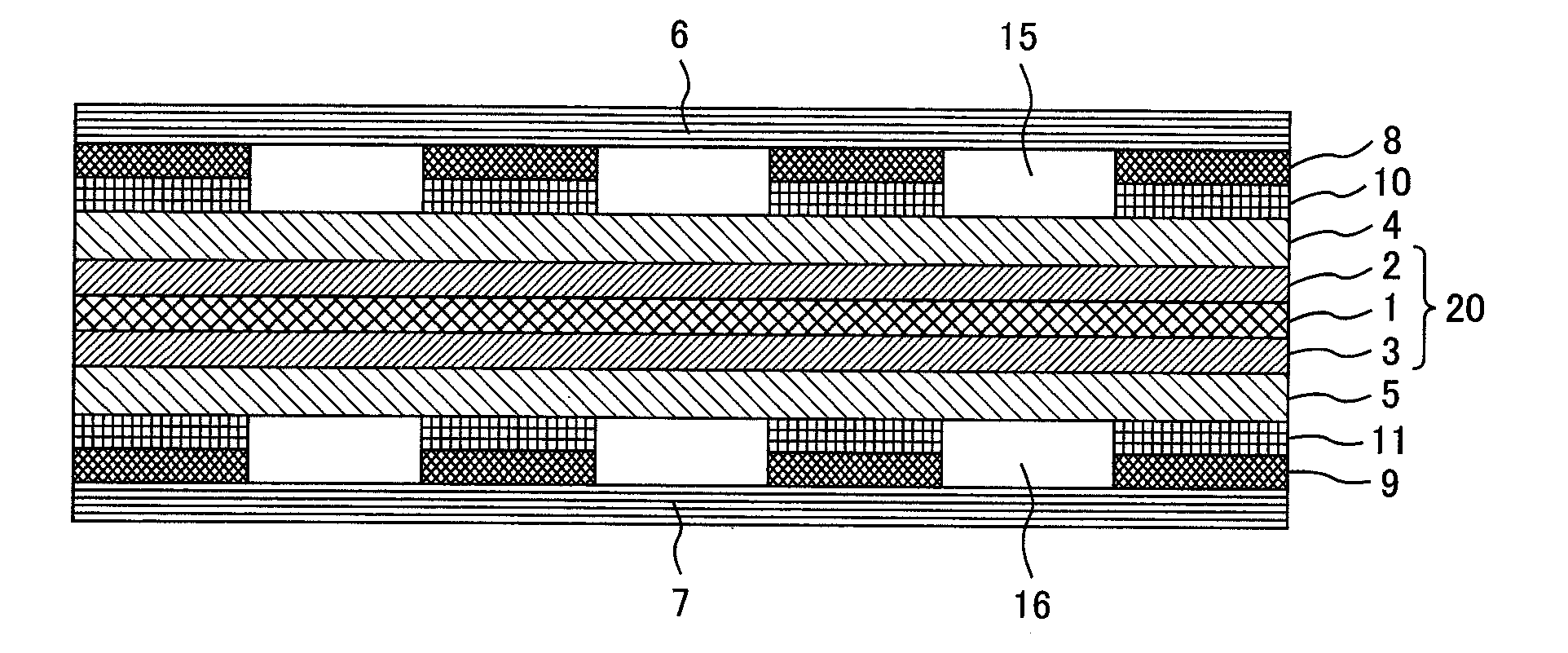
[0021]FIG. 1 is a schematic cross-sectional view showing a structure of a fuel cell in accordance with a first embodiment of the present invention.

[0022]A power generating unit cell includes a membrane electrode assembly (MEA) 20, a fuel electrode gas diffusion layer (GDL) 4, an oxidant electrode gas diffusion layer 5, a fuel bipolar plate 6, and an oxidant bipolar plate 7. The membrane electrode assembly 20 includes a solid polymer electrolyte membrane 1, an anode 2 and a cathode 3, and is sandwiched by the fuel electrode gas diffusion layer 4, the oxidant electrode gas diffusion layer 5, the fuel bipolar plate 6, and the oxidant bipolar plate 7. In FIG. 1, a fuel electrode is in the upper side of the power generating unit cell and an oxidant electrode is in the lower side thereof. The bipolar plates 6 and 7 have each gas channel. Hydrogen, which is fuel gas, flows to the fuel electrode gas diffusion layer 4 through the gas channel of the fuel bipolar plate 6 and reaches the anode ...

second embodiment

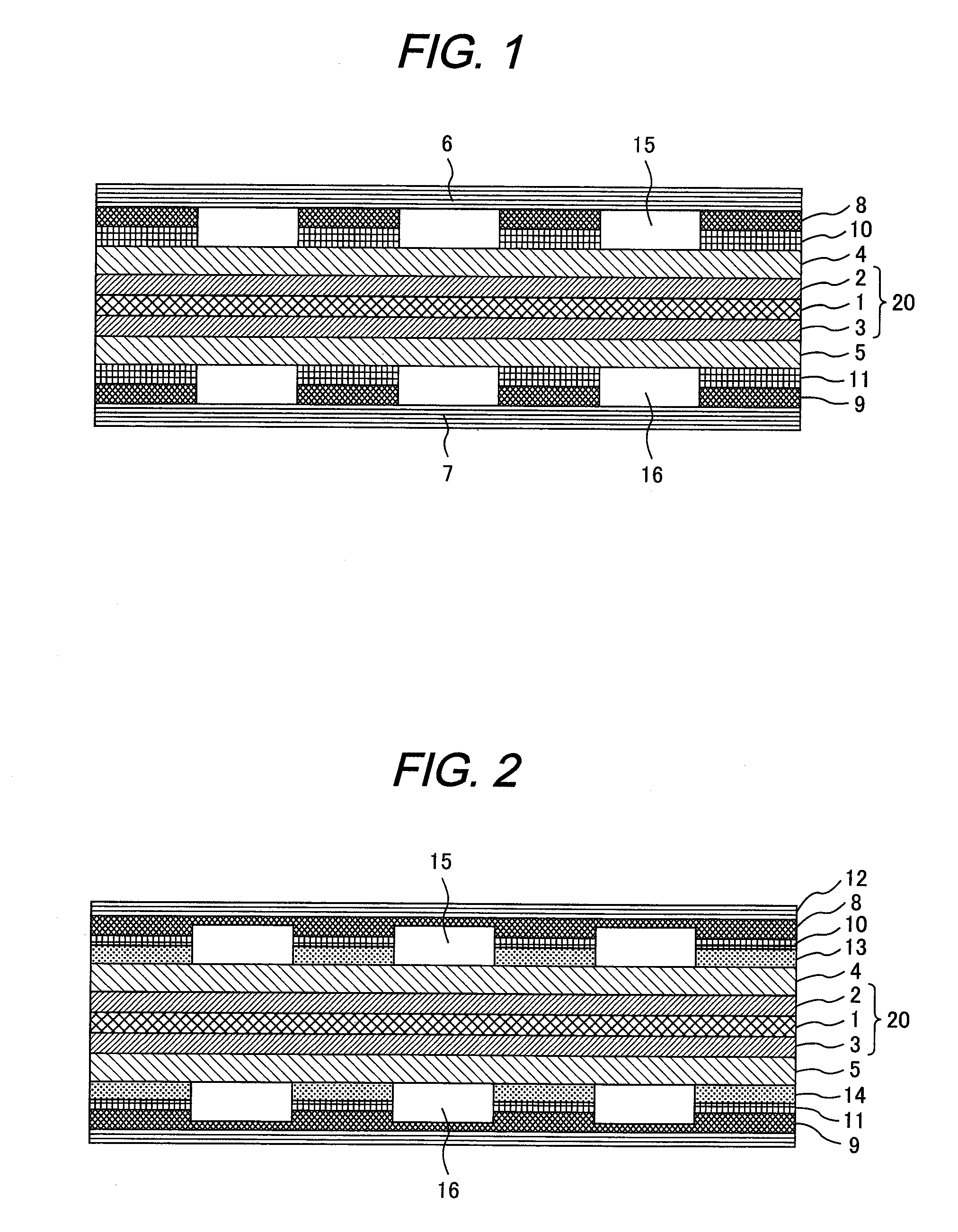
[0037]FIG. 2 is a schematic cross-sectional view showing a structure of a fuel cell according to a second embodiment of the present invention. In this structure, the ribs formed in a bipolar plate 12 are constituted of three layers. The cathode side of the fuel cell will be particularly described in the description below.

[0038]The bipolar plate 12 is a porous body formed of a conductive material, such as nickel, titanium, aluminum, carbon, magnesium, or an alloy containing them, for example a stainless alloy. The entire surface of the bipolar plate 12 is printed in the thickness of 5 μm-200 μm with the conductive material which is the same as the material for the first layer 9 of the ribs. On top of the surface, the first layer 9, the second layer 11, and a third layer 14 of the ribs are printed one by one. With respect to water repellency of the conductive material of each layer to be printed, the capillary force is set to satisfy the relations below:

Pgdl3rd, P2nd3rd, and P2nd1st

[...


PUM

PropertyMeasurementUnit
thicknessaaaaaaaaaa
conductiveaaaaaaaaaa
water repellencyaaaaaaaaaa

Abstract

The object of the present invention is to provide a bipolar plate for a fuel cell, suppressing the stay of condensed water in a gas diffusion layer and improving gas diffusion performance. The bipolar plate supplies reaction gas to a power generating surface and has a channel for the reaction gas. The channel is formed with ribs which are made of a conductive material laminate. The ribs have a porous structure and water repellency. The water repellency of the ribs is set lower than that of an adjacent gas diffusion layer. Thus, the condensed water can be moved from the gas diffusion layer to the ribs in an area where the gas diffusion layer and the ribs are in contact with each other. Therefore, deterioration of the gas diffusion performance due to the stay of the condensed water in the gas diffusion layer can be prevented.

Description

CLAIM OF PRIORITY[0001]The present application claims priority from Japanese Patent Application JP 2009-225881 filed on Sep. 30, 2009, the content of which is hereby incorporated by reference into this application.FIELD OF THE INVENTION[0002]The present invention relates to a fuel cell generating electric energy by chemical reaction of fuel and oxidant gas, and especially relates to a bipolar plate for a fuel cell.BACKGROUND OF THE INVENTION[0003]A polymer electrolyte fuel cell has a membrane electrode assembly (MEA) including a solid polymer electrolyte membrane, a fuel electrode catalyst layer (hereinafter referred to as “anode”) on one side of the solid polymer electrolyte membrane, and an oxidant electrode catalyst layer (hereinafter referred to as “cathode”) on the other side of the solid polymer electrolyte membrane, and gas diffusion layers (GDL) which are disposed on both sides of the membrane electrode assembly and made of porous carbon material. A power generating unit cel...

Claims


Application Information

Patent Timeline
Patent Type & Authority Applications(United States)
IPC IPC(8): H01M8/10H01M8/02
CPCH01M8/0206H01M8/0221H01M8/0226H01M8/0228Y02E60/50H01M8/0263H01M8/04171H01M2008/1095Y02E60/523H01M8/0258H01M8/2483
Inventor KOZAKAI, MASAYAOKUSAWA, TSUTOMUTAKAHASHI, KOSATAKE, HIROYUKI
Owner HITACHI LTD
Why Eureka
Try Eureka