
System and method for operating a turbocharged engine

Active Publication Date: 2011-04-14
GE GLOBAL SOURCING LLC
View PDF39 Cites 26 Cited by
  • Summary
  • Abstract
  • Description
  • Claims
  • Application Information

AI Technical Summary

Benefits of technology

[0006]In accordance with another exemplary embodiment of the present invention, a method for controlling a percentage of exhaust gas recirculation in a turbocharged system is disclosed. The method includes directing one portion of an exhaust flow from a set of predetermined cylinders among a plurality of cylinders of the engine through an exhaust gas recirculation system to an intake manifold of an engine. The method also includes directing another portion of the exhaust flow from the set of predetermined cylinders among the plurality of cylinders of the engine through an exhaust gas recirculation system to an exhaust manifold of the engine. The percentage of the other portion of the exhaust flow is controlled as a function of pressure ratio of a turboexpander of the exhaust gas recirculation system, speed of the turboexpander, or combinations thereof so as to substantially reducing specific fuel consumption and exhaust emissions of the engine.
[0007]In accordance with another exemplary embodiment of the present invention, a system having a controller configured to substantially reduce specific fuel consumption and exhaust emissions of an engine is disclosed.

Problems solved by technology

Unfortunately, engine efficiency, power output, fuel consumption, exhaust emissions, and other operational characteristics are less than ideal.
In addition, conventional techniques to improve one operational characteristic often worsen one or more other operational characteristic.
For example, attempts to decrease specific fuel consumption often cause increases in various exhaust emissions.
The usage of additional components for recirculation of exhaust gas increases specific fuel consumption (SFC) of the engine.
Also, conventional exhaust gas recirculation systems do not enable a uniform exhaust gas recirculation to different cylinders in a multicylinder engine.

Method used


Image

  • System and method for operating a turbocharged engine
  • System and method for operating a turbocharged engine
  • System and method for operating a turbocharged engine

Examples


Embodiment Construction

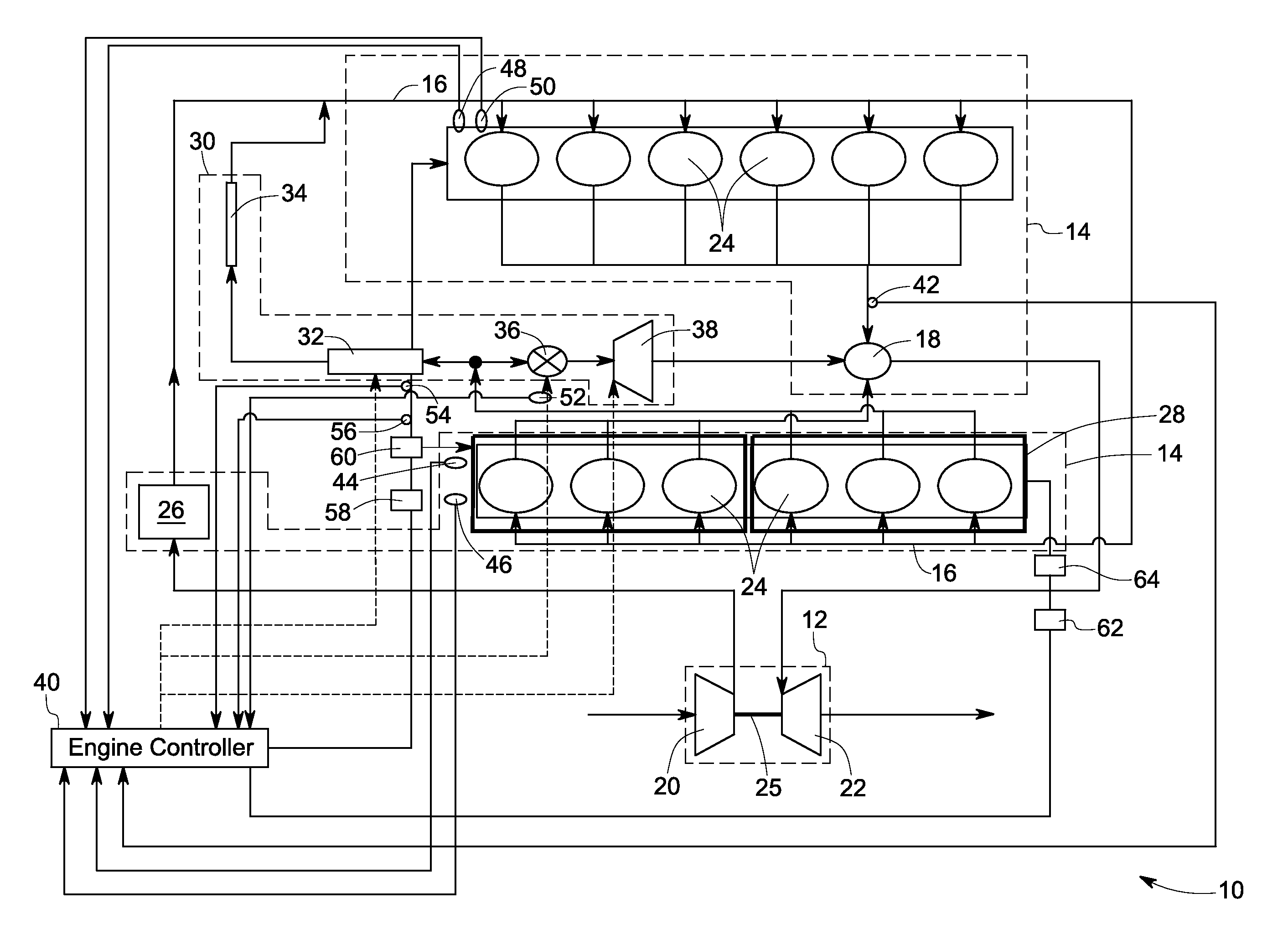
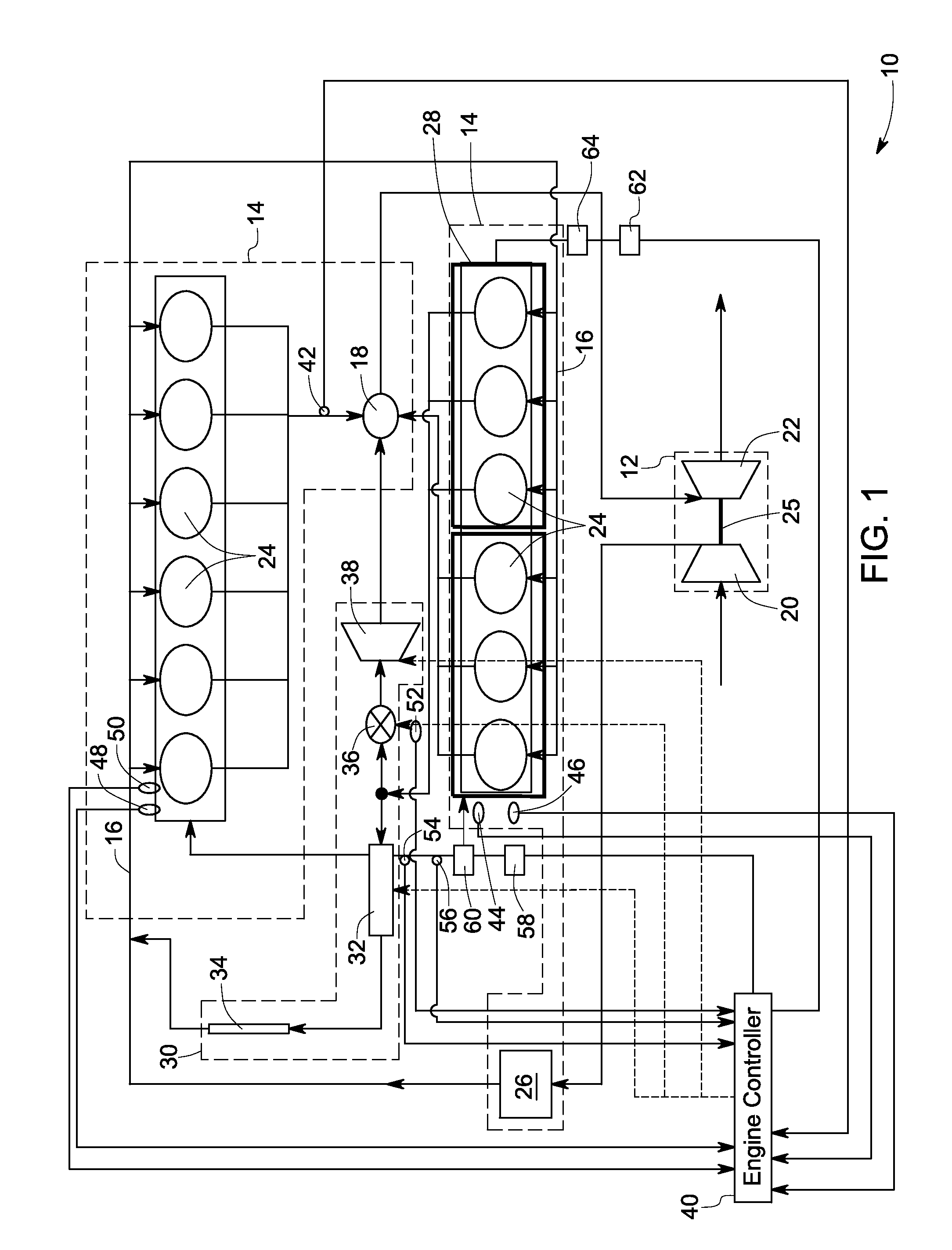
[0016]In accordance with the exemplary embodiments disclosed herein, a system and method of operating a turbocharged system is disclosed. The method includes substantially reducing specific fuel consumption and exhaust emissions of an engine by adjusting an exhaust flow from a set of predetermined cylinders among a plurality of cylinders of the engine through an exhaust gas recirculation system to an intake manifold, by adjusting a temperature of a cooler of the exhaust gas recirculation system, and by adjusting a fuel injection timing, in response to variance in a plurality of parameters. The parameters include a quantity of exhaust emissions, a maximum in-cylinder pressure of the engine, an engine load, an engine notch, engine speed, a percentage of exhaust gas recirculation through the exhaust gas recirculation system, a sulfur content in a fuel, a fuel injection pressure, or combinations of the parameters thereof.

[0017]Referring to FIG. 1, a turbocharged engine system 10 having ...


PUM


Abstract

A method includes substantially reducing specific fuel consumption and exhaust emissions of an engine by adjusting an exhaust flow from a set of predetermined cylinders among a plurality of cylinders of the engine through an exhaust gas recirculation system to an intake manifold, by adjusting a temperature of a cooler of the exhaust gas recirculation system, and by adjusting a fuel injection timing, in response to variance in a plurality of parameters of the engine.

Description

BACKGROUND[0001]The invention relates generally to a system and method for operating a turbo-charged compression-ignition engine and, specifically, to a system and method for substantially reducing specific fuel consumption and engine exhaust emission in a turbo-charged engine. More specifically, the invention relates to a system and method for enabling a uniform exhaust gas recirculation to different cylinders in a multicylinder engine.[0002]In a compression-ignition engine, such as a diesel engine, a fuel injection system injects fuel (e.g. diesel fuel) into compressed air within each of the engine cylinders to create an air-fuel mixture that ignites due to the heat and pressure of compression. Unfortunately, engine efficiency, power output, fuel consumption, exhaust emissions, and other operational characteristics are less than ideal. In addition, conventional techniques to improve one operational characteristic often worsen one or more other operational characteristic. For examp...

Claims


Application Information

Patent Timeline
IPC IPC(8): F02M7/00F02M25/07F02B33/44F02D41/00F01N11/00
CPCF02B3/06Y02T10/36F02B29/0437F02D35/023F02D41/0025F02D41/005F02D41/146F02D41/1466F02D41/401F02D2200/0611F02D2250/31F02M25/0707F02M25/0718F02M25/0727F02M25/0738F02M25/0739F02M25/0749Y02T10/44Y02T10/47F02D19/087F02D41/0082F02B29/0425F02M26/05F02M26/15F02M26/23F02M26/33F02M26/34F02M26/43Y02T10/30Y02T10/40
Inventor GOKHALE, MANOJ PRAKASHDESHPANDE, NILESH VINAYAK
Owner GE GLOBAL SOURCING LLC
Features
  • Generate Ideas
  • Intellectual Property
  • Life Sciences
  • Materials
  • Tech Scout
  • Unparalleled Data Quality
  • Higher Quality Content
  • 60% Fewer Hallucinations
Learn More