Method and device for optically examining the interior of turbid media

Active Publication Date: 2011-04-21
KONINKLIJKE PHILIPS ELECTRONICS NV
View PDF10 Cites 11 Cited by
  • Summary
  • Abstract
  • Description
  • Claims
  • Application Information

AI Technical Summary

Benefits of technology

[0011]It is an object of the present invention to improve the light efficiency of spectroscopic examinat

Problems solved by technology

However, an inherent problem occurring in spectroscopy on turbid media such as tissue is that, due to the relatively high amount of inherent scattering of light in tissue, the light emanating from the turbid medium under examination is strongly attenuated and, even more important, is of diffuse nature.
Light, once diffusive, cannot be collimated effectively and hence acquisition of an optical spectrum of light emanating from such a turbid medium is inefficient.
In other words, in a perfect optical system, the etendue is conserved; in imperfect real systems however, the etendue usually gets worse (i.e. to higher values).
Since the spectroscopy

Method used


Image

  • Method and device for optically examining the interior of turbid media
  • Method and device for optically examining the interior of turbid media
  • Method and device for optically examining the interior of turbid media

Examples


Example

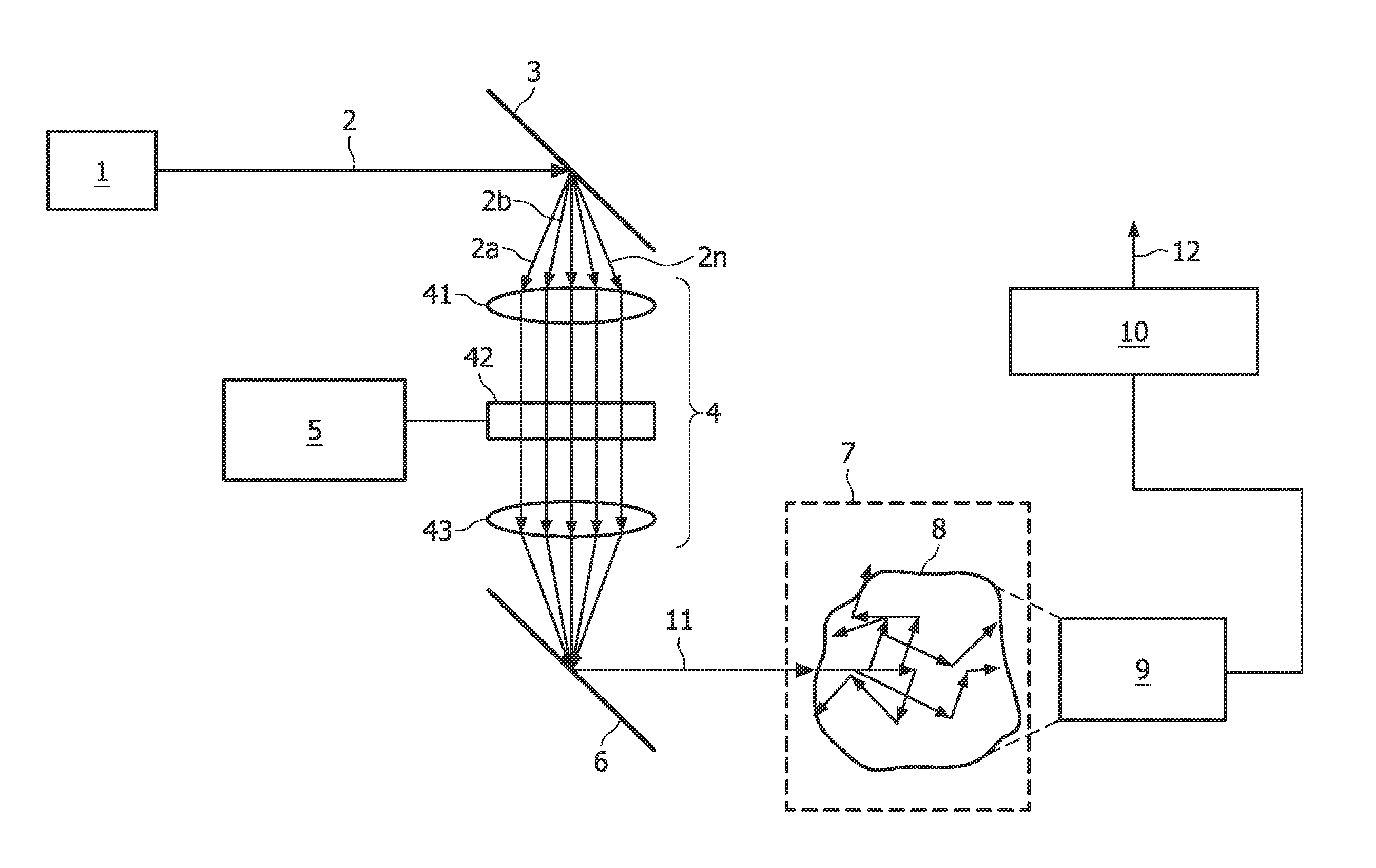
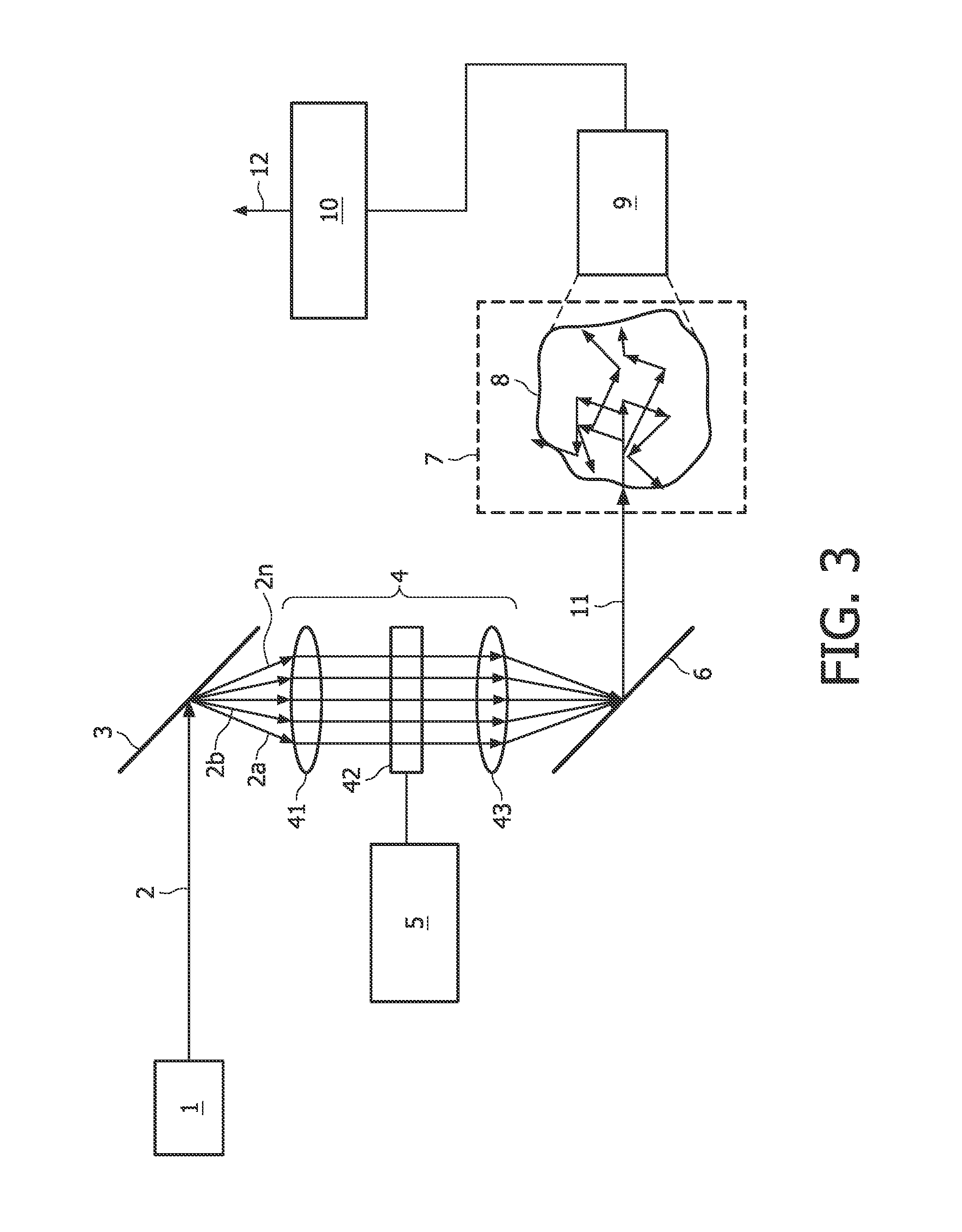
[0032]A first embodiment of the present invention will now be described with reference to FIG. 3. A device for examination of the interior of turbid media according to the first embodiment is formed by a spatial light modulation spectroscopy device. The device comprises a light source 1 emitting a collimated beam 2 of broad-band light, a band separator 3, a spatial light modulator 4, a light recombining unit 6, a measurement volume 7 for accommodating a turbid medium 8, a detector 9, and a demodulator 10.

[0033]The light source 1 is chosen such that white light with high power and brightness is emitted, i.e. the beam 2 comprises a continuous broad band of wavelengths covering a large plurality of wavelengths, preferably in the visible, IR, and / or NIR. The light source 1 may be pulsed. For example, the light source 1 is an extremely bright white light source based on super-continuum generation. For example, this is achieved by using intense femto-second light pulses propagating throug...

Example

Second Embodiment

[0047]A second embodiment will now be described with respect to FIG. 4. The second embodiment substantially corresponds to the first embodiment but comprises additional features which will be described. Therefore, identical components are denoted by identical reference signs and their description will be omitted.

[0048]The second embodiment differs from the first embodiment in that a beam splitter 20 is introduced in the light path behind the light modulating unit 42. This beam splitter couples a portion of each of the plurality of modulated wavelength bands out and directs it, via a lens 21, to a light analyzing unit 22. The light analyzing unit 22 analyzes the light distribution in the plurality of modulated wavelength bands and outputs the results as an output signal 23. The light analyzing unit 22 can e.g. be formed by a spectrometer.

[0049]The light analyzing unit 22 is further coupled to the modulation source 5 of the spatial light modulator 4 to provide a feedb...

Example

Third Embodiment

[0052]A third embodiment will now be described with respect to FIG. 5. The third embodiment substantially corresponds to the second embodiment but comprises an additional feedback as will be described below. Again, identical components are denoted by identical reference signs and their description will be omitted.

[0053]As can be seen in FIG. 5, an additional feedback loop from the detection side (behind the turbid medium) to the source side (upstream of the turbid medium) is provided. According to the shown example, the demodulator 10 outputs a feedback signal 26 which is provided to the modulation source 5 and thus to the spatial light modulator 4.

[0054]With this arrangement, further advantageous features can be realized. For example, the source spectrum, i.e. the spectrum of the spectrally encoded broad-band light which is used for illuminating the turbid medium 8, and the intensity of the different channels can be adaptively changed to the optimum probing spectrum...


PUM


Abstract

A method for optically examining the interior of turbid media is provided. The method comprises the steps: providing broad-band light (2); spatially separating a plurality of wavelength bands (2a, 2b, . . . , 2n) contained in the broad-band light; separately modulating the plurality of wavelength bands (2a, 2b, . . . , 2n); recombining the plurality of modulated wavelength bands to a beam (11) of spectrally encoded broad-band light; illuminating a turbid medium (8) with the beam (11) of spectrally encoded broad-band light; detecting light emanating from the turbid medium (8) with a detector (9) and demodulating the detected light with a demodulator (10) to provide spectroscopic information.

Description

FIELD OF INVENTION[0001]The present invention relates to a method and to a device for optically examining the interior of turbid media.BACKGROUND OF THE INVENTION[0002]In the context of the present application, the term turbid medium is to be understood to mean a substance consisting of a material having a high light scattering coefficient, such as for example an intralipid solution or biological tissue. The term light is to be understood to mean non-ionizing electromagnetic radiation, in particular with wavelengths in the range between 400 nm and 1400 nm.[0003]In the past decades, optics of turbid media such as biological tissue has become a widespread field of research and has found clinical applications in for instance monitoring (e.g. pulse oxymeter), cosmetics (e.g. port wine stain removal), and cancer treatment (e.g. photo dynamic therapy). Several techniques for optical imaging of turbid media (in particular for imaging biological tissue) are known, e.g. Optical Coherence Tom...

Claims


Application Information

Patent Timeline
IPC IPC(8): G01J3/447G01J3/28
CPCA61B5/0059G01J3/02G01J3/0229G01N21/49G01J3/10G01J3/42G01N21/4795G01J3/027
Inventor VAN DER MARK, MARTINUS BERNARDUS
Owner KONINKLIJKE PHILIPS ELECTRONICS NV
Why Eureka
Try Eureka