
Power factor correction controller, controlling method thereof, and electric power converter using the same

Inactive Publication Date: 2011-04-28
LITE ON TECH CORP +1
View PDF8 Cites 31 Cited by
  • Summary
  • Abstract
  • Description
  • Claims
  • Application Information

AI Technical Summary

Benefits of technology

[0012]In view of the aforementioned issues, an objective of the present invention is to make improvement for the power factor correction circuit in the critical conduction mode, so that the power factor correction circuit can be controlled to operate in different specific modes according to different values of the load, thereby reducing the power consumption of the electric power converter at a light load or a no-load condition and improving the energy transmission efficiency. Thus, the output voltage will experience less variation, which is favorable for optimization of the light load efficiency associated with the DC / DC converter of the next stage.
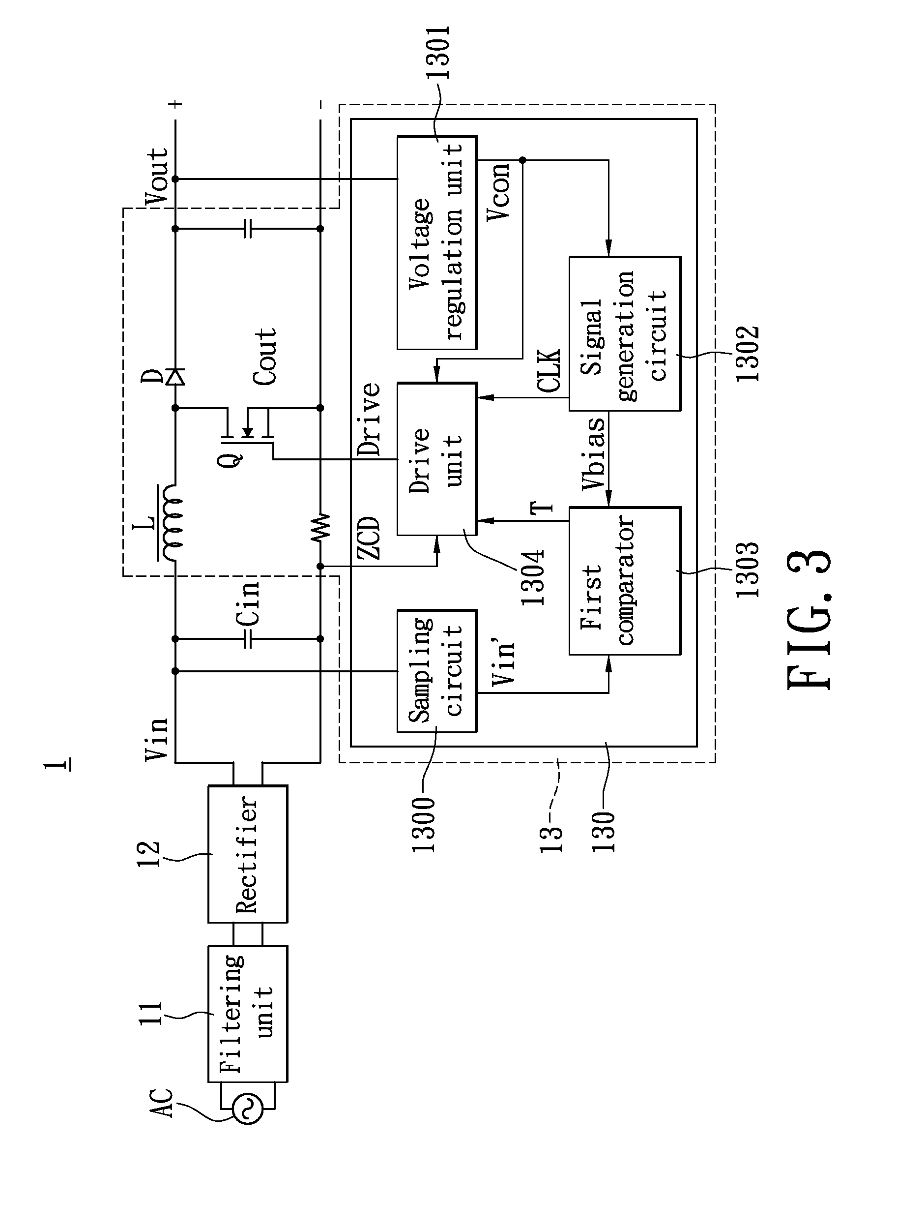
[0015]To achieve the above-mentioned objective, in yet another aspect of the present invention, an electric power converter is provided, which comprises a filtering unit, a rectifier, a filtering capacitor and a power factor correction circuit. The power factor correction circuit further comprises therein the power factor correction controller described in the above aspects. Thereby, through control operations of the power factor correction controller, power consumption of the electric power converter at a light load or a no-load condition is reduced, and the energy transmission efficiency of the electric power converter itself is improved.

Problems solved by technology

However, due to impedance characteristics of the filtering capacitor and the electrical appliance itself, a phase difference is generated between the input voltage and the input current.
This leads to a decrease in the power factor and consequently leads to electric power consumption, and exacerbates pollution to the power supply network.
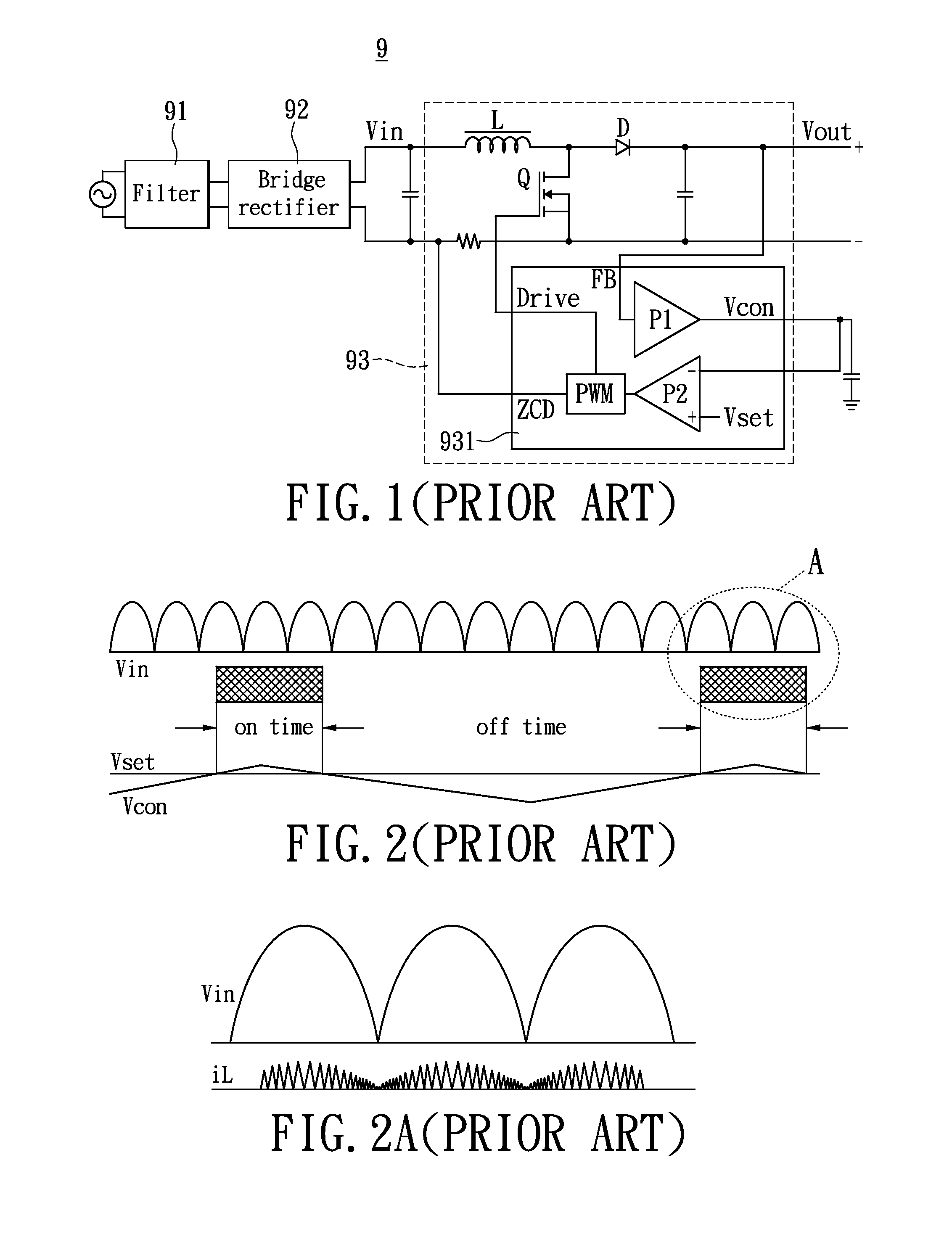
However, in the critical conduction mode, as the load decreases gradually, the switching frequency at which the power factor correction controller 931 controls the transistor Q increases, resulting in increased electric power consumption of the electric power converter 9.
Besides, near a zero-crossing point of the AC voltage, the input voltage Vin of the power factor correction circuit 93 also become smaller to cause a higher switching frequency of the transistor Q. This also results in considerable loss due to less power transmission, thereby decreasing the efficiency of the electric power converter 9.
Unfortunately, as the requirements on the light load efficiency and the no-load power consumption of the power supply become heightened increasingly, it becomes difficult for the frequency skipping controlling method described above to satisfy requirements of various international standards, e.g., standards relevant to energy saving established by Environmental Protection Agency (EPA) and Energy Star.
Moreover, the frequency skipping operation of the conventional power factor correction circuit 93 in the critical conduction mode under a light load condition causes large variations of the output voltage Vout, which is unfavorable for optimization of the light load efficiency associated with the DC / DC converter of the next stage and also unfavorable for improvement of the overall light load efficiency.

Method used


Image

  • Power factor correction controller, controlling method thereof, and electric power converter using the same
  • Power factor correction controller, controlling method thereof, and electric power converter using the same
  • Power factor correction controller, controlling method thereof, and electric power converter using the same

Examples


first embodiment

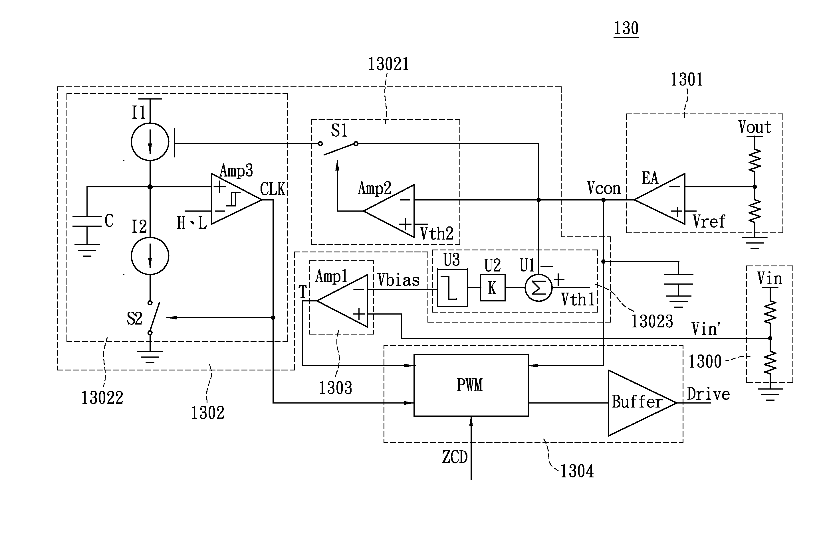
[0029]To describe design of the power factor correction controller 130 in detail, reference is made to FIG. 4 together, which is a schematic circuit diagram of the power factor correction controller according to the present invention. The power factor correction controller 130 further comprises a sampling circuit 1300, a voltage regulation unit 1301, a signal generation circuit 1302, a first comparator 1303 (Amp1) and a drive unit 1304. In order to comply with requirements of the input specification of the first comparator 1303, the sampling circuit 1300 is designed to be electrically connected to the rectifier 12 so as to receive the sinusoidal input voltage Vin and regulate the input voltage Vin into an input voltage Vin′ of a certain level for supplying to the first comparator 1303. As shown in FIG. 4, the sampling circuit 1300 may be, for example, designed as a voltage dividing circuit schematic.

[0030]As shown in FIG. 4, the voltage regulation unit 1301 comprises, for example, a...

second embodiment

[0049]Referring to FIG. 7 together, a schematic view of the operation modes versus the load value and switching frequency of the power factor correction circuit according to the present invention is demonstrated. With reference to this figure, controlling operations of the power factor correction circuit 13 with the aforesaid schematic of the power factor correction controller 130′ will be described.

[0050]First, when a heavy load condition presents and the control voltage Vcon is greater than or equal to the first threshold value (Vcon≧Vth1), the first switch S1 is turned off. In this state, operations are substantially the same as those in the state of the first embodiment when the control voltage Vcon is greater than or equal to the second threshold value Vth2. Accordingly, the drive unit 1304 is enabled to operate according to the enable signal and controls the transistor Q to operate in the critical conduction mode (CRM) according to the control voltage Vcon, the clock signal CL...


PUM


Abstract

A power factor correction controller is utilized for a power factor correction circuit in a critical conduction mode of an electric power converter. The power factor correction controller generates a control voltage according to an output voltage outputted from the electric power converter, and utilizes a first threshold value to detect the control voltage. The power factor correction controller can control the power factor correction circuit to operate in different modes according to various levels of a load. Therefore, an objective according to the present invention for reducing electric power consumption of the electric power converter in a light load or a no-load mode and improving energy transmission efficiency can be attained.

Description

BACKGROUND OF THE INVENTION[0001]1. Field of the Invention[0002]The present invention relates to a power factor correction controller, and in particular, to a power factor correction controller, a controlling method, and an electric power converter using the same in a critical conduction mode configured to improve light load efficiency and reduce electric power consumption under a light load or a no-load condition.[0003]2. Description of Related Art[0004]Most of electrical appliance products work with a direct current (DC) voltage, so the alternate current (AC) power supplied by the utility power network must be converted into DC power. The most common method is to use a diode bridge rectifier circuit and a filtering capacitor. This method is widely used because of the simple structure and low cost thereof. However, due to impedance characteristics of the filtering capacitor and the electrical appliance itself, a phase difference is generated between the input voltage and the input ...

Claims


Application Information

Patent Timeline
IPC IPC(8): G05F1/70
CPCY02B70/126H02M1/4225Y02B70/10Y02P80/10
Inventor ZHAO, QING-LINLI, MING-ZHUYE, ZHI-HONGTANG, XUE-FENGGUO, XINFENG, YU-LI
Owner LITE ON TECH CORP
Learn More